background image

FAX: +49 (0) 911 975 978 1 - TEL +49 (0) 911 975 978 0

Klingenhofstraße 51 - 90411  Nürnberg

Fehlerbeschreibung:

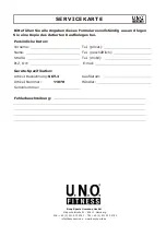
Bitte füllen Sie alle Angaben dieses Formulares vollständig aus und legen

Sie eine Kopie des datierten Kaufbeleges bei.

Persönliche Daten:

Vorname:
Name:
Straße:

PLZ, Ort:

Geräte-Spezifikation:

Artikel-Bezeichnung:
Artikel-Nummer:
Seriennummer:

Tel. (privat):
Tel. (geschäftlich):
Tel. (mobil):

E-mail:

Kaufdatum:
Händler:

SCT-3

11070

Beny Sports Germany GmbH

[email protected] · www.benysports.de

SERVICEKARTE

Содержание 11070

Страница 1: ...G Ge eb br ra au uc ch hs sa an nw we ei is su un ng g DE M Ma an nu ua al l GB Art Nr 11070 SCT 3 SCT 3 Montage Bedienungsanleitung Montage Bedienungsanleitung...

Страница 2: ...plos e Explosion drawing Disegni esplosi Explosietekening E U U 3 V 10 H I J K V 8 V 6 V 7 C V 11 V 19 V 11 V 19 V 8 S V 6 V 7 V 9 V 9 V 9 V 16 L R N V 12 V 13 V 14 V 15 V 13 V 12 V 14 V 15 V 16 M R O...

Страница 3: ...freien Platz um sich haben 6 Bevor Sie das Ger t benutzen stellen Sie sicher dass alle Muttern und Bolzen richtig festgezogen sind 7 Das Sicherheitslevel des Ger tes kann nur beibehalten werden indem...

Страница 4: ...x1 I x1 J x1 K x1 L x1 M x1 N x1 O x1 R x2 Q x1 P x1 S x1 T x1 U x1 V x1 M10 2PCS M10 60 2PCS 8 2 0 4PCS M8 20 6PCS M8 6PCS M8 40 6PCS M6 12 4PCS 8 24 M6 15 4PCS M8 13 12PCS 3 8 8PCS 14 19 M10 15 2PCS...

Страница 5: ...2 0 4PCS M8 20 2PCS M8 6PCS M8 40 6PCS M8 12 4PCS M8 14 8PCS 3 8 8PCS 14 19 M10 15 2PCS M10 10 2PCS M5 16 12PCS V 9 V 8 V 6 V 15 V 14 V 10 V 11 V 16 V 18 V 7 V 13 V 12 TOOLS V 1 1pcs V 2 1pcs V 3 1pc...

Страница 6: ...e die linke St tze P 1 am Hauptrahmen A mit 2 x Inbusschrauben V 9 an 2 Wiederholen Sie Schritt 1 f r die rechte Seite Bringen Sie die rechte St tze Q 1 am Hauptrahmen A mit 2 x Inbusschrauben V 9 an...

Страница 7: ...g V 11 2 x Inbusschraube V 19 und 2 x Sicherheits Inbusschraube V 17 4 Bringen Sie den rechten Handlauf D an der rechten St tze Q 1 an und befestigen Sie diesen mit 2 x Federring V 11 2 x Inbusschraub...

Страница 8: ...l Lagersatz der Pedal Baugruppe L an der Pedalarm Baugruppe A 26 mit 1 x Sicherheits Inbusschraube V 12 und 1 x Inbusschraube V 13 2 Als n chstes befestigen Sie die Halterung in der Mitte der Pedal Ba...

Страница 9: ...Schwungarm S am Hauptrahmen A mit 3 x Inbusschraube V 6 und 3 x Nylonmutter V 7 an 8 Bringen Sie den rechten Schwungarm T am Hauptrahmen A mit 3 x Inbusschraube V 6 und 3 x Nylonmutter V 7 an V 7x3 V...

Страница 10: ...ie rechte vordere und hintere F hrungsarmabdeckung J K mit 4 x Kreuzschlitzschraube V 8 an 10 1 Befestigen Sie die Cockpithalterung B 1 mit 2 x Sechskantbolzen V10 wie unten angezeigt 2 F hren Sie das...

Страница 11: ...fnung der Cockpithalterung B 1 wie unten angezeigt 2 Befestigen Sie den linken Handgriff F am Hauptrahmen A mit 2 x Sicherheits Inbusschraube V 17 und 2 x Inbusschraube V 18 3 Wiederholen Sie 1 und 2...

Страница 12: ...Platzieren Sie das Erdungskabel des Cockpits zwischen die Kreuzschlitzschraube U 3 und Unterlegscheibe und befestigen Sie dieses mit dem Maulschl ssel L6 V 3 14 Befestigen Sie die Abdeckung E an der C...

Страница 13: ...31 A 32 A 34 A 35 A 3 A 40 A 39 A 37 A 19 A 43 A 44 A 41 A 45 A 38 A 36 A 48 A 35 A 47 A 48 A 36 A 35 5 A 35 1 A 35 3 A 35 2 A 35 4 A 27 1 A 27 2 A 27 3 A 27 4 A 27 5 A 22 1 A 22 2 A 22 3 A 21 1 A 21...

Страница 14: ...r angezeigt 14 Up Taste Dr cken Sie die Up Taste um das Level zu steigern In der Programmauswahl dr cken Sie die Up Taste um ein Programm auszuw hlen Halten Sie die Up Taste f r 1 Sekunde gedr ckt um...

Страница 15: ...utzerdefinierbare Programm nutzen Sie die Up Down Tasten um die Einstellungen zu ndern und best tigen dann mit der OK Taste Geben Sie ber die Up Down Tasten Gewicht und Zeit ein und best tigen mit der...

Страница 16: ...n Tasten dr cken um das Widerstandslevel anzupassen Watt Modus Dr cken Sie die Herzfrequenz Programm Taste und w hlen dann das Watt Programm ber die Up Down Tasten aus Geben Sie Gewicht Zeit und Ziel...

Страница 17: ...n Wenn dieser beendet ist dr cken Sie eine beliebige Taste um den Test Modus zu verlassen Der Display Test besteht aus 10 Schritten jeder 1 Sekunde lang SCHRITT 1 Alle LEDs leuchten auf SCHRITT 2 Die...

Страница 18: ...BEDIENUNGSANWEISUNG 18 PROGRAMM ANZEIGEN Batterie fast leer Manuell K rperfett M nnlich Weiblich Gr e Gewicht Zeit Distanz Kalorien Alter Warm Up Anf nger Fortgeschritten Athlet Leerlauf...

Страница 19: ...BEDIENUNGSANWEISUNG 19 Fettverbrennung Training Benutzerdefiniert BENUTZER 1 BENUTZER 2 BENUTZER 3 BENUTZER 4 Speed Training 1 Speed Training 2 Extreme Training Sport Training 1 Sport Training 2...

Страница 20: ...BEDIENUNGSANWEISUNG 20 Herzfrequenz HRC 55 HRC 65 HRC 75 HRC 85 WATT Zuf llige Steigung Zuf llig 1 Zuf llig 2 Steigung 1 Steigung 2 Steigung 3...

Страница 21: ...BEDIENUNGSANWEISUNG 21 Herzfrequenz zu hoch Herzfrequenz zu hoch Pausiert Niedrige Herzfrequenz Gelb Normale Herzfrequenz Gr n Hohe Herzfrequenz Rot Kein Signal Mehrfarbig...

Страница 22: ...24 Unterlegscheibe 1 A 25 Sechskantbolzen M8 x 20 4 A 26 Pedalarm Baugruppe L 1 A 26 1 Pedalarm L 1 A 26 2 Kugellager 2 A 26 3 Kugellagerstange 1 A 26 4 Wellenscheibe 2 A 26 5 Kupferbuchse 2 A 26 6 K...

Страница 23: ...1 P 1 St tze L 1 P 2 Mutter M10 1 P 3 Verstellbarer Standfu 1 Q St tzen Baugruppe R 1 Q 1 St tze R 1 Q 2 Mutter M10 1 1 Q 3 Verstellbarer Standfu R Gummisohle 2 S Schwungarm L 1 T Schwungarm R 1 U Coc...

Страница 24: ...e of free space all around it 6 Before using the equipment check the nuts and bolts are securely tightened 7 The safety level of the equipment can only be maintained if it is regularly examined for da...

Страница 25: ...J x1 K x1 L x1 M x1 N x1 O x1 R x2 Q x1 P x1 S x1 T x1 U x1 V x1 M10 2PCS M10 60 2PCS 8 2 0 4PCS M8 20 6PCS M8 6PCS M8 40 6PCS M6 12 4PCS 8 24 M6 15 4PCS M8 13 12PCS 3 8 8PCS 14 19 M10 15 2PCS M10 10...

Страница 26: ...CS M8 20 2PCS M8 6PCS M8 40 6PCS M8 12 4PCS M8 14 8PCS 3 8 8PCS 14 19 M10 15 2PCS M10 10 2PCS M5 16 12PCS V 9 V 8 V 6 V 15 V 14 V 10 V 11 V 16 V 18 V 7 V 13 V 12 TOOLS V 1 1pcs V 2 1pcs V 3 1pcs V 4 1...

Страница 27: ...LE INSTRUCTION 1 Insert the Left Connection Tube P 1 into the Main Frame Set A fasten with 2 pcs of Hex Screw V9 2 Follow the same assembly procedures to assemble the right side 27 V 3 V 9x4 V 9 P V 3...

Страница 28: ...ion Tube P 1 fasten using attachment hardware V 11 2 V 19 2 and V 17 2 4 Insert Right Handle Connection Tube D into Right Connection Tube Q 1 fasten using attachment hardware V 11 2 V 19 2 and V 17 2...

Страница 29: ...wn below 1 First step is to attach the bearing end of Left Pedal Post Set L onto the attachment mechanism using attaching hardware V 12 1 and V 13 1 2 Second step is to attach the center support of th...

Страница 30: ...ION 7 Attach Left Swing Post Set S using the attachment hardware V 6 3 and V 7 3 as shown below 8 Follow the same assembly procedures as above to assemble the right side V 7x3 V 6x3 V 3 V 5 V 7 V 6 S...

Страница 31: ...8 4 2 Follow the same assembly procedures as below to assemble the right side 10 1 Attach the Computer Post B 1 using attachment hardware V10 2 as shown below 2 Insert the computer cable A 46 in the o...

Страница 32: ...the Computer Post B 1 as shown in the photo s below 2 Fasten the Left Fixed Handlebar Set F onto the attachment tube using the attachment hardware V 17 2 and V 18 2 3 Follow the same assembly procedur...

Страница 33: ...33 ASSEMBLE INSTRUCTION 13 Insert the ground wire of the computer between Cross Screw U 3 and washer and attach with Wrench L6 V 3 14 Attach Computer Post Cover E onto computer post B 1 E...

Страница 34: ...31 A 32 A 34 A 35 A 3 A 40 A 39 A 37 A 19 A 43 A 44 A 41 A 45 A 38 A 36 A 48 A 35 A 47 A 48 A 36 A 35 5 A 35 1 A 35 3 A 35 2 A 35 4 A 27 1 A 27 2 A 27 3 A 27 4 A 27 5 A 22 1 A 22 2 A 22 3 A 21 1 A 21...

Страница 35: ...the Level Up button to increase the level setting Once in program selection press Level Up button to select program profile Press and hold the Up button for 1 second and the count up will increase at...

Страница 36: ...OK button to confirm Continue and set up Weight and Time with the Up Down buttons and then press OK to confirm Press the Quick Start button to start the exercise Resistance is set to a default of 1 Pr...

Страница 37: ...to change the level WATT Control Mode Press the Heart Rate Program then press the Up Down buttons and select Watt Control Continue and set up Weight Time and Target Watt press the number key to set u...

Страница 38: ...ick Start button at the same time to test the next process Enter Display testing When finished with the testing press any key to leave It has 10 steps each step is 1 second long STEP 1 All LED lights...

Страница 39: ...TION INSTRUCTION 39 PROGRAM DISPLAYS Low Power Manual Body Fat Set Up Female Height Setting Weight Setting Time Setting Distance Setting Calories Setting Age Setting Warm Up Beginner Intermediate Adva...

Страница 40: ...OPERATION INSTRUCTION 40 Fat Burn Training Personal USER 1 USER 2 USER 3 USER 4 Speed Training 1 Speed Training 2 Extreme Training Sport Training 1 Sport Training 2...

Страница 41: ...OPERATION INSTRUCTION 41 Heart Rate HRC 55 HRC 65 HRC 75 HRC 85 WATT Random Hill Random 1 Random 2 Hill 1 Hill 2 Hill 3...

Страница 42: ...OPERATION INSTRUCTION 42 HRC Break Heart Rate Workout Done Paused Low Heart Rate Yellow Normal Heart Rate Green High Heart Rate Red No Signal Multi Color...

Страница 43: ...23 Flat washer 4 A 24 Power wire 1 A 25 Hex screw M8 x 20 4 A 26 Left pedal post 1 A 26 1 Left pedal post 1 A 26 2 Bearing 2 A 26 3 Bearing post 1 A 26 4 Waved washer 14 5 x 21 x T0 3 2 A 26 5 Copper...

Страница 44: ...t connection tube 1 P 2 M10 Hex nut 1 P 3 Adjustable foot cushion 1 Q Right connection tube set 1 Q 1 Right connection tube 1 Q 2 M10 Hex Nut 1 1 Q 3 Adjustable foot cushion R Cushion plate 2 S Left s...

Страница 45: ...lares vollst ndig aus und legen Sie eine Kopie des datierten Kaufbeleges bei Pers nliche Daten Vorname Name Stra e PLZ Ort Ger te Spezifikation Artikel Bezeichnung Artikel Nummer Seriennummer Tel priv...

Отзывы: