background image

USER GUIDE

Control Operation-Service

USER GUIDE

 Control Operation - Service 2

u-line.com

SAFETY • INSTALLATION & INTEGRATION • OPERATING INSTRUCTIONS • MAINTENANCE • 

SERVICE

DOOR ALERT NOTIFICATION

When the door is left open for more than 5 minutes:

An audible tone will sound for several seconds every

minute.

“dr” will appear in display.

Close door to silence alert and reset. 

VIEWING ACTUAL TEMPERATURE

In viewing temperature in these modes any offsets are 
taken into account. This means that if you place a therm-
istor in a known temperature, let’s say ice water, it may 
not read the 32°F that you would assume. If the control 
offset was preset at -3°F while you placed the thermistor 
in an icebath, the actual thermistor reading when viewing 
actual temperature would read 35°F. In the unit this would 
cause the cabinet to push itself 3° cooler. To view pure 
thermistor readings you must go into the service menu 
and choose the correct option.

To view the thermistor temperature, push and release the 
up and down keys. The display will show the corrected 
refrigerator temperature.

SHOWROOM MODE

This mode is designed to show units in a display environ-
ment. When in this mode the only functions will be the 
control and cabinet lights. The compressor, fans, etc. will 
not operate. To enter/exit this mode hold the light key 
and the power key for 5 seconds. The display will flash 
once and beep and the degree symbol will begin to flash. 

When the degree symbol is flashing the unit will allow the 
use of the control for demonstrations. The unit can be left 
in this mode indefinitely. 

SERVICE MODE

This mode has options available for service diagnostics. 
To enter the mode hold the hidden key for 10 seconds. 
The display will show “0.” When in this mode use the up 
and down arrows to select the desired option. The LIGHT 
key is the ENTER key and will initiate the function. If 
changing a setting, you must press the LIGHT key again 
to retain the changed setting. To exit the service mode 
scroll to option “0” and press the LIGHT key. After five 
minutes of not touching any keys the mode will also exit 
automatically.

CONTROL FUNCTION QUICK GUIDE
FUNCTION

COMMAND

DISPLAY/OPTIONS

ON/OFF

Press 

 and release 

Unit will immediately turn ON or OFF

Toggle lights

Press 

 and release to leave interior light 

on for 3 hours

Glass door wine captains and beverage centers 
only.

Adjust refrigerator 
temperature

Push 

 and release 

When the “F” or “C” in the display is flashing, 
push 

 to adjust the set point 

temperature.

View temperature in unit

Push 

 and release together

The display will flash and then toggle from set 
point to temperature in unit.

Toggle between F/C

Hold the 

 for five seconds

The display will change units.

or

or

and

and

ACCESS SERVICE MODE

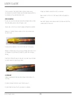
To access the service menu for this model, remove the 
two screws that hold the display together.
Remove display circuit board. Press and hold the far left 
button on the display circuit board.

Press and Hold

USER GUIDE

 Control Operation - Service 3

u-line.com

SAFETY • INSTALLATION & INTEGRATION • OPERATING INSTRUCTIONS • MAINTENANCE • 

SERVICE

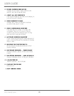
SERVICE MODE GUIDE
1. THERMISTOR 1 — ZONE

This shows the pure thermistor reading with no


offsets taken into account.

2. THERMISTOR 2 — EVAPORATOR

This shows the pure thermistor reading with no


offsets taken into account.

3.

Does not apply to this model.

4.

Does not apply to this model.

5. THERMISTOR 1 — ZONE OFFSET

(DO NOT MAKE AN ADJUSTMENT TO THIS WITHOUT


CONTACTING TECH LINE:

+1.414.354.0300

)

This calibration is only to be used if actual


temperature at thermistor #1 is off from set


point.
By adjusting the offset higher we can force the


unit to drive the temperature down below the set


point. (example: adjusting from 0 to +2 will drop


the unit temperature 2 degrees)

6. THERMISTOR 2 — EVAPORATOR OFFSET 

(DO NOT MAKE AN ADJUSTMENT TO THIS WITHOUT


CONTACTING TECH LINE:

+1.414.354.0300

)

7. THERMISTOR 3 — AMBIENT OFFSET 

Not

adjustable.

8.

Does not apply to this model.

9. THERMISTOR 2 — SET POINT MINUS 

OFFSET

This shows the thermistor reading with offsets


taken into account.

10.

Does not apply to this model.

11.

Does not apply to this model.

12.ADJUST DEFROST INTERVAL — 3 TO 24 

HOURS

This will adjust the interval between defrosts


from 3 to 24 hours. Adjusting from the factory


settings may cause undesired temperature in


the refrigerator section.

13.ADJUST DEFROST DURATION — 0 TO 99 

MINUTES

The length of the defrost can be adjusted 0 to 99


minutes long. The other defrost parameters still


apply. Lengthening a defrost may cause higher


than normal temperatures in the refrigerator


section.

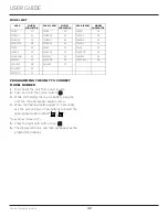
  #

Service Mode Menu Item

1

View thermistor #1 (no offsets)

2

View thermistor #2 (no offsets)

3

View thermistor #3 (no offsets)

4

View thermistor #4 (no offsets)

5

Adjust thermistor #1 offset

6

Adjust thermistor #2 offset

7

Adjust thermistor #3 offset

8

Adjust thermistor #4 offset

9

View thermistor #2 set point no offsets

10

View thermistor #3 set point no offsets

11

View thermistor #4 set point no offsets

12

Adjust defrost interval 3 to 24 hours

13

Adjust defrost duration 0 to 99 minutes

14

View error log

15

Clear error log

16

Adjust thermistor #1 differential

17

Adjust evaporator fan delay in minutes (start of cooling 

cycle)   0 - 99 minutes

18

Adjust evaporator fan delay in minutes (after cooling 

cycle stops)   0 - 99 minutes

19

Individual component toggle

20

Model number indicator

21

Light all LED segments of display

22

View defrost cycles

23

View compressor run time

24

Activate defrost/harvest

25

Restore factory defaults

26

View software version - main board

27

View software version - user interface 

28

Login period

29

Factory test mode

0

Exit service mode

NAVIGATE SERVICE MODE

Use up or down arrows to scroll through the menu.

Use the light bulb key to enter or exit menu. If values 

have been changed, they will be saved when exiting.

SERVICE MODE GUIDE

39

Содержание UHRF124WS01A

Страница 1: ...USER GUIDE SERVICE MANUAL Model UHRF124 WS01A...

Страница 2: ...ip Bracket General Installation Grille Installation Door Swing Door Adjust Interior Adjustments Maintenance Free Standing Kit Cleaning Cleaning Condenser Extended Non Use Operating Instructions First...

Страница 3: ...HT PRODUCT RIGHT PLACE RIGHT TEMPERATURE PRODUCT INFORMATION Looking for additional information on your product User Guides Spec Sheets CAD Drawings and Product Warranty information are available digi...

Страница 4: ...oderate personal injury property or equipment damage This unit contains R600a Isobutane which is a flammable hydrocarbon It is safe for regular use Do not use sharp objects to expedite defrosting Do n...

Страница 5: ...e so children may not easily climb inside If the unit is being removed from service for disposal check and obey all federal state and local regulations regarding the disposal and recycling of refriger...

Страница 6: ...ures may reduce the unit s ability to reach low temperatures and or reduce ice production on applicable models For best performance keep the unit out of direct sunlight and away from heat generating e...

Страница 7: ...it Always keep your working area dry NOTICE Electrical installation must observe all state and local codes This unit requires connection to a grounded three prong polarized receptacle that has been pl...

Страница 8: ...CAUTION Unit can NOT be installed behind a closed cabinet door CUTOUT DIMENSIONS PRODUCT DIMENSIONS REAR FRONT TOP SIDE 13 1 8 333 mm 18 3 8 467 mm 22 1 8 562 mm 10 267 mm 14 1 8 359 mm 26 680 mm 22...

Страница 9: ...cording to each unit s electrical specifications requirements Side by Side Installation with Bracket 1 Slide both units out so screws on top of units are easily accessible 2 Remove screws as shown bel...

Страница 10: ...oles and attach to unit with two screws removed in step 2 using a T 25 Torx driver Tighten screws fully 4 Gently push unit into position Be careful not to entangle the electrical cord or water line if...

Страница 11: ...ing s rear height Shorten the unit height in the front by adjusting the front legs This allows the unit to be gently tipped into the opening Readjust the front legs to level the unit after it is corre...

Страница 12: ...HARP and can be easily damaged Removing the grille 1 Disconnect power to the unit 2 Loosen the two screws 1 3 Remove grille 2 from unit Installing the grille 1 Align cabinet and grille holes and secur...

Страница 13: ...its have a zero clearance for the door to open 90 when installed adjacent to cabinets Stainless Steel models require 2 1 8 54 mm door clearance to accommodate the handle if installed next to a wall Wa...

Страница 14: ...not remove top and bottom hinge screws using a Torx T 25 screwdriver 3 Align door squarely with cabinet 4 Make sure gasket is firmly in contact with cabinet all the way around the door no gaps 5 Tigh...

Страница 15: ...nge 1 Remove bottom hinge from cabinet using a 1 4 socket 2 Remove corresponding screws on opposite side of cabinet On some models there may be a nut behind one or both screws on either side Install b...

Страница 16: ...abinet Available at u line com To install the kit 1 Remove grille see GRILLE INSTALLATION section 2 Place shell accessory over front and back of cabinet base aligning holes of shell accessory with the...

Страница 17: ...rned off during installation simply press and the unit will immediately switch on To turn the unit off press If the temperature displayed is different than selected the unit is progressing towards the...

Страница 18: ...ble Sabbath Mode Press and hold for 5 seconds and release The oF oC symbol will flash briefly after 5 seconds Interior light and display will go dark and remain so until user resets mode unit continue...

Страница 19: ...es Not all bottles and cans will fit on every shelf and wine rack Larger diameter champagne and Magnum bottles only fit on wine racks when noted on the product specifications When determining capaciti...

Страница 20: ...e shelf from unit by pulling out 3 Insert the shelves as follows 1 To move to a different position in the unit insert shelf at an angle approximately 15 20 over the rib in the side of the unit where y...

Страница 21: ...eel to become blurred Rust not cleaned up promptly can penetrate the surface of the stainless steel and complete removal of the rust may not be possible Integrated Models To clean integrated panels us...

Страница 22: ...tive flooring the unit must be removed from cabinetry To defrost 1 Disconnect power to the unit 2 Remove all products from the interior 3 Prop the door in an open position 2 in 50 mm minimum 4 Allow t...

Страница 23: ...g on environmental conditions more or less frequent cleaning may be necessary WARNING Disconnect electric power to the unit before cleaning the condenser WARNING DO NOT touch the condenser fins The co...

Страница 24: ...evaporator allow ice to thaw naturally 4 Clean and dry the interior of the unit Ensure all water has been removed from the unit 5 The door must remain open to prevent formation of mold and mildew Open...

Страница 25: ...ates Evaporator Refrigerant flowing through an evaporator may sound like boiling liquid Condenser Fan Air moving through a condenser may be heard Automatic Defrost Drain Pan Water may be heard drippin...

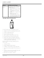
Страница 26: ...check the actual product temperature in the unit 1 Partially fill a plastic nonbreakable bottle with water 2 Insert an accurate thermometer 3 Tighten the bottle cap securely 4 Place the bottle in the...

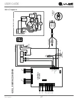
Страница 27: ...TO COMPRESSOR PURPLE WHITE PAN HEATER 115 VOLT PLUG ORANGE RED PURPLE BLACK YELLOW LIGHT BLUE BLACK WHITE If Applicable CONTROL BOARD FUSE WATER VALVE HOT GAS VALVE ICEMAKER ASSEMBLY SW C GREEN W YELL...

Страница 28: ...replace the part in question The part that caused the damage must be returned to U Line in its entirety The part must be clearly labeled with the serial number of the unit it was removed from the dat...

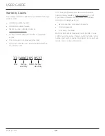
Страница 29: ...r warranty labor Units must be registered prior to warranty submittal Customers may register at www U Line com A proof of purchase is required We also accept the following information to update warran...

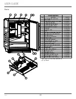
Страница 30: ...FAN 80 54310 00 14 FREEZER DOOR ASSEMBLY 80 54308 00 15 GASKET DOOR 80 55498 00 16 GLASS SHELF ASSEMBLY 80 55660 00 17 GRILLE ASSEMBLY 24 BLACK 80 55597 01 18 HINGE ASSEMBLY BLACK 80 55595 02 19 HINGE...

Страница 31: ...ranty status Please provide the model serial number part number and part description Some parts will require color or voltage information If U Line requires the return of original parts we will inform...

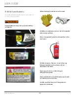
Страница 32: ...ust observe all federal state and local laws regarding refrigerants Gloves and Eye Protection must be used R 600a is considered non toxic but is flammable when mixed with air Keep a dry powder type fi...

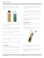
Страница 33: ...pump and recovery equipment should be at least 10 feet from the work area It is recommended that a simple LPG gas detector is on site during service Ensure that all R 600a is removed from the system p...

Страница 34: ...is left within the system prior to repair simple venting is not sufficient Evacuate and charge with dry nitrogen for leak checks Repair leaks or replace system parts as required When re brazing the sy...

Страница 35: ...ll a Schrader Type access port on the compressor process stub Evacuate the system to 100 microns prior to charging Weigh in the R 600a charge using a refrigerant scale run compressor an extra two minu...

Страница 36: ...cold near inlet Outlet below room temperature Lower than normal Partial Restriction Somewhat lower than normal vacuum Warm near room temperature Very hot Top passes warm Lower passes cool near room te...

Страница 37: ...h are not hot or frozen Compressor Specifications EM2C46CLC 115V REFRIGERANT R600a VOLTAGE 115V 127V FREQUENCY 50Hz START WINDING 5 20 8 Q at 25 C 77 F RUN WINDING 7 19 8 Q at 25 C 77 F LRA 8 0A FLA 2...

Страница 38: ...and reset VIEWING ACTUAL TEMPERATURE In viewing temperature in these modes any offsets are taken into account This means that if you place a therm istor in a known temperature let s say ice water it...

Страница 39: ...display will flash and then toggle from set point to temperature in unit seconds The display will change units or ACCESS SERVICE MODE To access the service menu for this model remove the two screws t...

Страница 40: ...T DURATION 0 TO 99 MINUTES The length of the defrost can be adjusted 0 to 99 minutes long The other defrost parameters still apply Lengthening a defrost may cause higher than normal temperatures in th...

Страница 41: ...s will show the number of minutes the compressor has run in the prior cycle or current cycle if the compressor was running when service mode was entered 24 ACTIVATE DEFROST HARVEST Turns on the hot ga...

Страница 42: ...ing digits appear 3 5 seconds use the up and down arrow buttons to select the appropriate model number See Above Model List 5 Press the light bulb button once 6 The display will blink and then will ap...

Страница 43: ...2 Evap Fan Cond Fan 22 RE336 1A Compressor Top Left Valve Bot Right Valve Light 1 Light 2 Evap Fan Evap Fan 2 Cond Fan 23 RE515 1A Compressor Light 1 Light 2 Evap Fan Cond Fan 25 RE524 1A Compressor...

Страница 44: ...improper use maintenance installation service repair acts of God fire flood or other natural disasters The product must be installed operated and maintained in accordance with your product s User Guid...

Отзывы: