background image

USER GUIDE

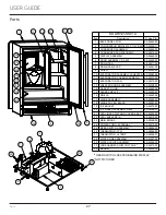
Parts

Parts

SUARI121-SS01A

Item

Description

U-Line P/N

1

BACK PANEL RI121

80-55660-02

2

COMPRESSOR EM2C46CLC,115V,R600 80-55658-11

3

CONDENSER ASSEMBLY

80-55660-03

4

CONDENSER FAN W/SCREWS

80-54014-00

5

DISPLAY ASSEMBLY

80-55660-04

6

DOOR ASSEMBLY, SS 430

80-55660-05

7

DRAIN PAN

80-54217-00

8

DRAIN PAN, EVAP

80-54361-00

9

DRIER

80-54055-00

10 EVAPORATOR ASSEMBLY W/HEATER 80-55583-00
11 EVAPORATOR COVER W/SCREWS

80-54312-00

12 EVAPORATOR FAN

80-54310-00

13 FREEZER DOOR ASSEMBLY

80-54308-00

14 GASKET, DOOR

80-55660-06

15 GLASS SHELF (1)

80-54559-00

16 GRILLE

80-55660-08

17 HINGE ASSEMBLY

80-55595-00

18 HINGE COVER, BLACK

80-55543-00

19 ICE BUCKET

80-54370-00

20 ICE MAKER ASSEMBLY R600

80-54589-01

21 LED LIGHT STRIP AND COVER ASSY

80-54000-00

22 LEG LEVELERS (4)

80-54019-00

23 MAIN BOARD

80-55398-00

24 POWER CORD, EXTERNAL *

80-55519-00

25 REED SWITCH ASSEMBLY **

80-54805-00

26 THERMISTOR (1PC)

80-54006-00

27 THERMISTOR, HI TEMP 

80-54006-01

28 WATER LINE ASSEMBLY

80-54357-00

29 WATER VALVE ASSEMBLY

80-54356-00

30 WIRE HARNESS,LOW VOLTAGE *

80-55519-02

* NOT PICTURED

** REED SWITCH LOCATED BEHIND DISPLAY

11

8

18

2

29

7

3

4

9

22

23

27

1

19

16

26

17

10

12

14

15

6

20

5

21

13

30 MAGNET *

80-54902-00

27

Содержание UARI121-SS01A

Страница 1: ...USER GUIDE SERVICE MANUAL Model UARI121 SS01A...

Страница 2: ...nstallation Environmental Requirements Electrical Cutout Product Dimensions Water Hookup General Installation Grille Installation Door Swing Door Adjust Interior Adjustments Maintenance Cleaning Clean...

Страница 3: ...HT PRODUCT RIGHT PLACE RIGHT TEMPERATURE PRODUCT INFORMATION Looking for additional information on your product User Guides Spec Sheets CAD Drawings and Product Warranty information are available digi...

Страница 4: ...oderate personal injury property or equipment damage This unit contains R600a Isobutane which is a flammable hydrocarbon It is safe for regular use Do not use sharp objects to expedite defrosting Do n...

Страница 5: ...e so children may not easily climb inside If the unit is being removed from service for disposal check and obey all federal state and local regulations regarding the disposal and recycling of refriger...

Страница 6: ...ures may reduce the unit s ability to reach low temperatures and or reduce ice production on applicable models For best performance keep the unit out of direct sunlight and away from heat generating e...

Страница 7: ...it Always keep your working area dry NOTICE Electrical installation must observe all state and local codes This unit requires connection to a grounded three prong polarized receptacle that has been pl...

Страница 8: ...ons PREPARE SITE Your U Line product has been designed for either free standing or built in installation When built in your unit does not require additional air space for top sides or rear However the...

Страница 9: ...water line should be looped into 2 coils This will allow the unit to be removed for cleaning and servicing Make certain that the tubing is not pinched or damaged during installation WARNING Connect to...

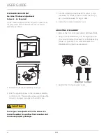
Страница 10: ...r feature in bushing with flat screwdriver 5 Thread water line through back panel hole with bushing 6 Locate water valve inlet and connect to valve 7 Turn on water supply and check for leaks 8 Reinsta...

Страница 11: ...y Use a level to confirm the unit is level Level should be placed along top edge and side edge as shown INSTALLATION 1 Plug in the power electrical cord 2 Gently push the unit into position Be careful...

Страница 12: ...talled Removing the grille Note Grille and display are attached The length of the display wire is sufficient to allow access to the front base components 1 Disconnect power to the unit 2 Remove the tw...

Страница 13: ...its have a zero clearance for the door to open 90 when installed adjacent to cabinets Stainless Steel models require 2 1 8 54 mm door clearance to accommodate the handle if installed next to a wall Wa...

Страница 14: ...und the door no gaps 4 Tighten bottom hinge screws 5 Tighten top hinge screws REVERSING THE DOOR Location of the unit may make it desirable to mount the door on the opposite side of the cabinet The hi...

Страница 15: ...inge Install two or three screws depending on model Replace nuts if used Install top hinge and door 1 Rotate door 180o and lift the door on to the bottom hinge 2 Install hinge that was used on the opp...

Страница 16: ...rned off during installation simply press and the unit will immediately switch on To turn the unit off press If the temperature displayed is different than selected the unit is progressing towards the...

Страница 17: ...ble Sabbath Mode Press and hold for 5 seconds and release The oF oC symbol will flash briefly after 5 seconds Interior light and display will go dark and remain so until user resets mode unit continue...

Страница 18: ...ration You may hear the compressor or fan motor the water valve or ice dropping into the ice bucket CAUTION NEVER use an ice pick knife or other sharp instrument to separate cubes Shake the ice bucket...

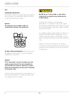
Страница 19: ...an adjustment to the screw can cause the water to overflow the ice maker and can cause property damage 3 Turn the adjusting screw toward the minus sign clockwise for smaller cubes or toward the plus s...

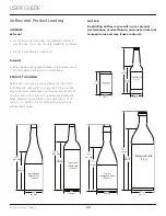
Страница 20: ...es Not all bottles and cans will fit on every shelf and wine rack Larger diameter champagne and Magnum bottles only fit on wine racks when noted on the product specifications When determining capaciti...

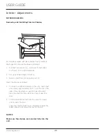
Страница 21: ...e shelf from unit by pulling out 3 Insert the shelves as follows 1 To move to a different position in the unit insert shelf at an angle approximately 15 20 over the rib in the side of the unit where y...

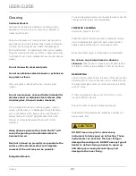
Страница 22: ...eel to become blurred Rust not cleaned up promptly can penetrate the surface of the stainless steel and complete removal of the rust may not be possible Integrated Models To clean integrated panels us...

Страница 23: ...tive flooring the unit must be removed from cabinetry To defrost 1 Disconnect power to the unit 2 Remove all products from the interior 3 Prop the door in an open position 2 in 50 mm minimum 4 Allow t...

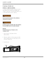
Страница 24: ...g on environmental conditions more or less frequent cleaning may be necessary WARNING Disconnect electric power to the unit before cleaning the condenser WARNING DO NOT touch the condenser fins The co...

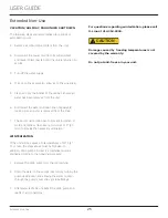
Страница 25: ...st remain open to prevent formation of mold and mildew Open door a minimum of 2 50 mm to provide the necessary ventilation WINTERIZATION If the unit will be exposed to temperatures of 40 F 5 C or less...

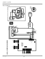
Страница 26: ...MPRESSOR PURPLE WHITE PAN HEATER 115 VOLT PLUG ORANGE RED PURPLE BLACK YELLOW LIGHT BLUE BLACK WHITE If Applicable CONTROL BOARD FUSE WATER VALVE HOT GAS VALVE ICEMAKER ASSEMBLY SW C GREEN W YELLOW BL...

Страница 27: ...00 14 GASKET DOOR 80 55660 06 15 GLASS SHELF 1 80 54559 00 16 GRILLE 80 55660 08 17 HINGE ASSEMBLY 80 55595 00 18 HINGE COVER BLACK 80 55543 00 19 ICE BUCKET 80 54370 00 20 ICE MAKER ASSEMBLY R600 80...

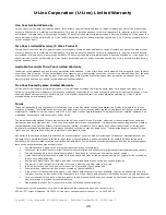
Страница 28: ...improper use maintenance installation service repair acts of God fire flood or other natural disasters The product must be installed operated and maintained in accordance with your product s User Guid...

Отзывы: