PAGE 2 OF 12
0421 IH-670
ASSEMBLY CONTINUED
5. Place the scale on the stable, level surface on which
it is intended to be used.
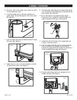
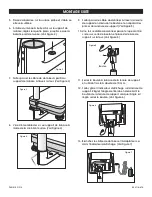
6. Using the bubble level on the base bracket as a
guide, adjust the four leveling feet until scale is level.
(See Figure 2)
7. Feed the data cable from the base bracket through
the tower. (See Figure 3)
8. Tighten the set screws in the base bracket using the
included Allen wrench. (See Figure 4)
9. Feed the data cable through the support bracket by
unscrewing the knob and pulling the support bracket
pieces apart. (See Figure 5)
10. Once data cable is threaded through support
bracket as shown, tighten the knob and place the
support bracket on the tower. (See Figure 5)
11. Tighten the bolt at the base of the support bracket
using a 10 mm box wrench.
12. Slide the display Indicator onto the support bracket.
Adjust the angle of the display by loosening the
knob on the support bracket. Tighten the knob when
finished adjusting the angle. (See Figure 6)
13. Plug the data cable and the AC adapter into the
display indicator. (See Figure 7)
Figure 2
Figure 3
Figure 4
Figure 5
Figure 6
Figure 7
Knob


