background image

PAGE 2 OF 12 

0814 IH-3415

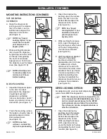
MOUNTING INSTRUCTIONS CONTINUED

TAPE MOUNTING  

CONTINUED

4.  Open the dispenser by 

pushing up on the release   

latch. The latch is on the 

bottom back edge of the 

dispenser in the center. 

(See Figure 8) 

NOTE: See "Keyed 
Locking Option" if you 
would like to convert 
your dispenser to a 
keyed system.

5.  While pushing the release 

latch, open the dispenser 

by placing your other hand 

on the top, and guiding  

the front cover forward.  

Apply pressure from inside 

the dispenser over the taped 

area. (See Figures 9-10)

NOTE: Allow dispenser 
to remain empty for a 
minimum of 8 hours 
before loading.  

SCREW MOUNTING

1.  Important! Dispenser opens 

to the front. For ideal 

placement, the dispenser 

should be mounted 3" 

above any countertop, 

fixture or obstruction, and 2" 

below any cabinet, fixture or 

obstruction. (See Figure 11)

2.  Clean the mounting surface 

thoroughly using any type of  

general purpose cleaner 

and a paper towel.  

(See Figure 12)

NOTE: Be certain 
surface is completely 

dry before proceeding.  

3.  Open the dispenser by 

pushing up on the release 

latch. The latch is on the 

bottom back edge of the 

dispenser in the center. 

(See Figure 13) 

NOTE: See "Keyed 
Locking Option" if you 
would like to convert 
your dispenser to a 
keyed system.

4.  While pushing the release 

latch, open the dispenser  

by placing your other hand 

on the top, and guiding  

the front cover forward.  

(See Figure 14)

5.  Hold the dispenser against 

the wall in the proper 

position and mark the 

appropriate slots. Drill holes 

in marked slots. Attach 

dispenser to the wall with 

the wall anchors and screws 

provided. You may choose 

to remove a portion of the 

protective backing from 

the tape to help hold the 

dispenser in position as you  

complete the installation.  

(See Figure 15)

KEYED LOCKING OPTION

For added security, your new foam dispensing 

system has a KEYED locking option. 

NOTE: The dispenser has been shipped to you 
in the manual, NO KEY REQUIRED mode. If you 
wish to convert your dispenser to the KEYED 
locking mode, please follow the instructions. 

The conversion can be completed before or 
after the installation. 

1.  Open the dispenser by 

pushing up on the release   

latch. The latch is on the 

bottom back edge of the 

dispenser in the center. 

While pushing the release 

latch, open by placing 

your other hand on the top, 

and guiding the front cover 

forward. (See Figure 16) 

INSTALLATION CONTINUED

Figure 8

Figure 9

Figure 10

2"

11"

7.5"

3"

Figure 11

Figure 13

Figure 14

Figure 15

Figure 16

Figure 12

Key

Содержание H-3415

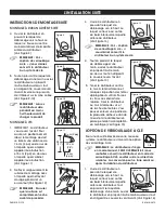
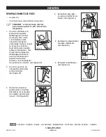
Страница 1: ...ountertop fixture or obstruction and 2 below any cabinet fixture or obstruction See Figure 5 2 Clean the mounting surface thoroughly using any type of general purpose cleaner and a paper towel See Figure 6 NOTE Be certain surface is completely dry before proceeding 3 Remove the protective backing from the tape pad on the back of the dispenser Make certain that the mounting surface is clean and dry...

Страница 2: ...ee Figure 13 NOTE See Keyed Locking Option if you would like to convert your dispenser to a keyed system 4 While pushing the release latch open the dispenser by placing your other hand on the top and guiding the front cover forward See Figure 14 5 Hold the dispenser against the wall in the proper position and mark the appropriate slots Drill holes in marked slots Attach dispenser to the wall with ...

Страница 3: ...he dispenser can be converted back to the NO KEY REQUIRED mode Complete steps 2 and 3 and insert the latch piece with the SLOTTED SIDE TOWARD the wall LOADING THE DISPENSER 1 Open by pushing up on the release latch use key if you have converted to the keyed locking mode The latch is on the bottom back edge in the center See Figure 22 While pushing the release latch open by placing your other hand ...

Страница 4: ...se latch open the dispenser by placing your other hand on the top and guide the front cover forward See Figure 29 3 Flip up cover of battery compartment in upper right side See Figure 30 4 Unhook battery terminals and remove battery pack Replace all 6 AA batteries with new batteries See Figure 31 5 Return battery pack to space and attach battery terminals See Figure 32 6 Close dispenser See Figure...

Страница 5: ...e ser instalado 7 6 cm 3 arriba de cualquier superficie accesorio u obstáculo y 5 cm 2 abajo de cualquier gabinete accesorio u obstáculo Vea Diagrama 5 2 Limpie bien la superficie de instalación con cualquier tipo de limpiador multiusos y una toalla de papel Vea Diagrama 6 NOTA Cerciórese de que la superficie esté totalmente seca antes de proceder 3 Retire el respaldo de la almohadilla adhesiva de...

Страница 6: ...vertir su despachador al sistema con llave 4 Mientras presiona el seguro para liberación abra el despachador colocando su otra mano en la parte superior y dirija el frente de la cubierta hacia adelante Vea Diagrama 14 5 Sostenga el despachador contra la pared en la posición correcta y marque las ranuras correspondientes Perfore los orificios en las ranuras que marcó Fije el despachador a la pared ...

Страница 7: ...tirse de nuevo al modo QUE NO REQUIERE LLAVE Siga los pasos 2 y 3 e inserte la pieza del seguro con el LADO RANURADO HACIA la pared CARGUE EL DESPACHADOR 1 Abra el despachador elevando el seguro para liberación utilice la llave si está en la modalidad de cerrar con llave El seguro está en la parte de abajo al centro atrás del despachador Vea Diagrama 22 Mientras presiona el seguro para liberación ...

Страница 8: ...la parte SUPERIOR y dirija el frente de la cubierta hacia adelante Vea Diagrama 29 3 Levante la cubierta del compartimento de las baterías en la parte superior derecha Vea Diagrama 30 4 Desconecte las terminales de las baterías y retire el paquete de baterías Reemplace las 6 baterías AA con las nuevas baterías Vea Diagrama 31 5 Regrese el paquete de baterías a su lugar y conecte las terminales de ...

Страница 9: ...ge devrait se faire à une distance de 7 6 cm 3 po au dessus de n importe quel comptoir appareil ou obstruction et 5 cm 2 po en dessous n importe quel cabinet appareil ou obstruction Voir Figure 5 2 Nettoyer soigneusement la surface de montage avec n importe quel nettoyant d usage général et un essuie tout Voir Figure 6 REMARQUE S assurer que la surface est complètement sèche avant de procéder 3 En...

Страница 10: ...teur Voir Figure 13 REMARQUE Voir L option de verrouillage à clé si vous désirez convertir le distributeur à un system de clé 4 Tout en pressant le loquet de déblocage d une main ouvrez le distributeur en plaçant l autre main au dessus tout en dirigeant le couvercle vers l avant Voir Figure 14 5 Tenez le distributeur contre le mur à l endroit désiré et marquez la position des fentes appropriées à ...

Страница 11: ...uteur peut être reconverti au mode CLÉ NON REQUISE Suivre les étapes 2 et 3 puis insérer l ensemble de loquet le CÔTÉ À FENTES faisant face au mur CHARGEMENT DE LA DISTRIBUTRICE 1 Ouvrez le distributeur en pressant le loquet de déblocage vers le haut ou encore avec la clé si le distributeur a été converti au mode de verrouillage à clé Le loquet se trouve au centre du bord inférieur de la partie ar...

Страница 12: ... déblocage d une main ouvrez le distributeur en plaçant l autre main au dessus tout en dirigeant le couvercle vers l avant Voir Figure 28 2 Ouvrir le couvercle du compartiment des piles en haut à droite Voir Figure 29 3 Décrochez les bornes du bloc piles et le retirer Remplacez les six 6 piles AA usagées par des piles neuves Voir Figure 30 4 Remettre le bloc piles en place et rettacher les bornes ...

Отзывы: