


SARA-G3 series - System Integration Manual
UBX-13000995 - R06
Objective Specification
System description
Page 50 of 218
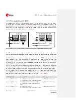
1.9.1.2
UART AT interface configuration
The UART interface is the only AT command interface on SARA-G3 series modules. UART is configured
as described in
(for information about further settings, refer to the
u-blox AT Commands
Manual [2]).
Interface
AT Settings
Comments
UART interface
AT interface: enabled
AT command interface is enabled by default on the UART physical interface
AT+IPR=0
Automatic baud rate detection enabled by default
AT+ICF=0
Automatic frame format recognition enabled by default
AT&K3
HW flow control enabled
AT&S1
DSR line set ON in data mode5 and set OFF in command mode
5
AT&D1
Upon an ON-to-OFF transition of DTR, the DCE enters online command mode5 and
issues an OK result code
AT&C1
Circuit 109 changes in accordance with the Carrier detect status; ON if the Carrier is
detected, OFF otherwise
MUX protocol: disabled
Multiplexing mode is disabled by default and it can be enabled by AT+CMUX
command.
The following virtual channels are defined for SARA-G350 modules:
Channel 0: control channel
Channel 1 – 5: AT commands / data connection
Channel 6: GNSS tunneling
The following virtual channels are defined for SARA-G300 and SARA-G310 modules:
Channel 0: control channel
Channel 1 – 2: AT commands / data connection
Table 9: Default UART AT interface configuration
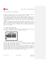
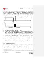
1.9.1.3
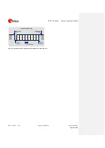
UART signal behavior (AT commands interface case)
At the module switch-on, before the UART interface initialization (as described in the power-on sequence
reported in
), each pin is first tri-stated and then is set to its relative internal reset
state.
6
At the end of the boot sequence, the UART interface is initialized, the module is by default in
active-mode, and the UART interface is enabled.
The configuration and the behavior of the UART signals after the boot sequence are described below. See
section 1.4 for definition and description of module operating modes referred to in this section.
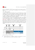
RXD signal behavior
The module data output line (
RXD
) is set by default to the OFF state (high level) at UART
initialization. The module holds
RXD
in the OFF state until the module does not transmit some data.
5
Refer to the
u-blox AT Commands Manual
[2] for the definition of the interface data mode, command mode and online command
mode.
6
See the pin description table in the SARA-G3 series Data Sheet [1].