


SARA-G3 series - System Integration Manual
UBX-13000995 - R06
Objective Specification
System description
Page 38 of 218
1.6
System function interfaces
1.6.1
Module power-on
The power-on sequence of SARA-G3 series modules is initiated in one of these ways:
Rising edge on the
VCC
pin to a valid voltage as module supply (i.e. applying module supply)
Low level on the
PWR_ON
pin (normally high with external pull-up) for an appropriate time period
RTC alarm (i.e. pre-programmed scheduled time by AT+CALA command)
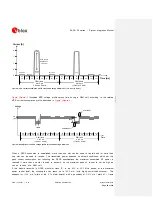
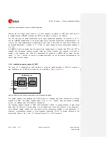
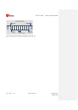
1.6.1.1
Rising edge on VCC
When a SARA-G3 module is in the not-powered mode, it can be switched on by applying the
VCC
supply.
The module is switched on when the voltage rises up to the
VCC
normal operating range minimum limit
(3.35 V) starting from a voltage value lower than 2.25 V, and with a proper voltage slope: the voltage
at the
VCC
pins must ramp from 2.5 V to 3.2 V within 4 ms to switch on the module. When the
VCC
voltage is stabilized at its nominal value within the normal operating range, the module can be switched
on by a low level on
PWR_ON
pin (see section 1.6.1.2) or by RTC alarm (see section 1.6.1.3).
If the
PWR_ON
input pin is held low during the
VCC
apply phase, the SARA-G3 module switches on
when voltage rises up to the
VCC
normal operating range minimum limit (3.35 V).
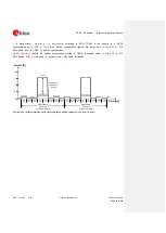
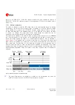
1.6.1.2
Low level on PWR_ON
When a SARA-G3 module is in the power-off mode (i.e. switched off with valid
VCC
supply
maintained), the module can be switched on by forcing a low level on the
PWR_ON
input pin at least
for 5 ms.
The electrical characteristics of the
PWR_ON
input pin are different from the other digital I/O interfaces.
The input voltage thresholds are slightly different since the
PWR_ON
input pin is tolerant of voltages up to
the module supply level. The detailed electrical characteristics are described in
SARA-G3 series Data
Sheet [1].
There is no internal pull-up resistor on the
PWR_ON
pin: the pin has high input impedance and is
weakly pulled to the high level by the internal circuit. Therefore the external circuit must be able to hold
the high logic level stable, e.g. providing an external pull-up resistor (for further design-in guidelines refer
to section 2.2.1).
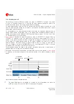
1.6.1.3
RTC alarm
When a SARA-G3 module is in the power-off mode (i.e. switched off with valid
VCC
supply
maintained) and the RTC timing (32 kHz reference clock) is available, the module can be switched on
by an RTC alarm previously programmed by AT command at a scheduled time (refer to the
u-blox AT
Commands Manual [2], AT+CALA command). The internal RTC block system will then initiate the module
boot sequence by instructing the Power Management Unit to turn on power. Also included in this setup is
an interrupt signal from the RTC block to indicate to the baseband processor that an RTC event has
occurred.
The RTC timing is automatically generated by the 32.768 kHz reference clock provided by the internal
oscillator on SARA-G350 modules. A valid external 32.768 kHz signal must be provided at the
EXT32K