


NORA-W10 series - System integration manual
UBX-22005601 - R04
Design-in
Page 18 of 56
C1-Public
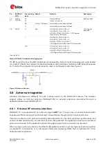
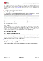
summarizes each of the available antenna options.
Figure 5: Antenna options
As NORA-W10 modules cannot be mounted arbitrarily, the placement should be chosen with
consideration so that it does not interfere with radio communication. NORA-W106 modules include
an internal PCB trace antenna that cannot be mounted in a metal enclosure. No metal casing or
plastics using metal flakes should be used. Avoid metallic based paint or lacquer as well. NORA-W101
modules offer more freedom as an external antenna can be mounted further away from the module.
⚠
When integrating the u-blox reference design into an end-product, the application designer is
solely responsible for any unintentional emission levels produced by the end-product.
⚠
According to the FCC regulations, the transmission line from the module’s antenna pin to the
antenna or antenna connector on the host PCB is considered part of the approved antenna design.
Therefore, module integrators must either follow exactly one of the antenna reference designs
used in the module’s FCC type approval or certify their own designs.
3.2.1
RF transmission line design (NORA-W101)
RF transmission lines, such as the ones from the
ANT
pad up to the related antenna connector or up
to the related internal antenna pad, must be designed so that the characteristic impedance is as close
as possible to 50
.