


NORA-W10 series - System integration manual
UBX-22005601 - R04
Design-in
Page 17 of 56
C1-Public
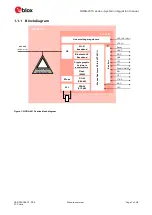
3
Design-in
Follow the design guidelines stated in this chapter to optimize the integration of NORA-W10 series
modules in the final application board.
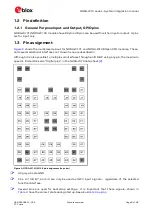
3.1
Overview
Although all application circuits must be properly designed, there are several points that require
special attention during application design. A list of these points, in order of importance, follows:
•
Module antenna connection:
ANT
Pad
Antenna circuits affect the RF compliance of all applications that include the certification
schemes related to the module. To maintain compliance and subsequent certification of the
application design, it is important to observe the applicable parts of antenna schematic and layout
design described in
•
Module supply:
VCC
,
VCC_IO
, and
GND
pins.
Supply circuits can affect the RF performance. It is important to observe the schematic and layout
design for these supplies. See also
. Modules normally include several
supply pins described in the pin out of the NORA-W10 data sheet
•
High-speed interfaces:
UART
pins.
High-speed interfaces are a potential source of radiated noise that can affect the regulatory
compliance standards for radiated emissions. It is important to follow the schematic and layout
design recommendations described in the
General high-speed layout guidelines
•
System functions:
RESET_N
, GPIO and other System input and output pins
Careful utilization of these pins in the application design is required to ensure correct boot up and
system operation. Ensure that the voltage level is correctly defined during module boot. It is
important to follow the schematic and layout design recommendations described in the
•
Other pins:
ADC
,
CAN,
and NC pins.
Careful utilization of these pins is required to guarantee proper functionality. It is important to
follow the schematic and layout design recommendations described in the
UART_TX, UART_RXD
and
SYS_BOOT
pins should be made accessible in order to flash regulatory
compliance testing firmware.
3.2
Antenna interface
NORA-W10 modules support the following antenna types:
•
Internal antenna included on the NORA-W106 module.
•
Integrated antenna on the main application PCB. Typically, a patch antenna mounted on the main
PCB or application housing, which is then connected to the NORA-W101 RF pin through a
transmission line.
•
External Antenna. Typically, a monopole antenna connected to the NORA-W101 RF pin through a
coaxial cable and U.FL connector on the main PCB.