


NORA-W10 series - System integration manual
UBX-22005601 - R04
Module integration
Page 14 of 56
C1-Public
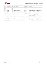
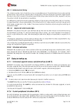
Pin
ESP32-S3
GPIO
State during
boot
Default
Behavior
Description
F7,
H7
GPIO0,
GPIO46
00
Download Boot
Booting mode
01
Invalid, do not use
10
Pull-up*, Pull-down* Normal Boot from internal Flash
11
Normal Boot from internal Flash
J9
GPIO3
0
N/A
EFUSE_DIS_USB_JTAG = 0,
EFUSE_DIS_PAD_JTAG = 0,
EFUSE_STRAP_JTAG_SEL=1 JTAG signal
from on-chip JTAG pins
JTAG signal
selection
1
EFUSE_DIS_USB_JTAG = 0,
EFUSE_DIS_PAD_JTAG = 0,
EFUSE_STRAP_JTAG_SEL=1
JTAG signal from USB Serial/JTAG controller
D/C
EFUSE_DIS_USB_JTAG = 0,
EFUSE_DIS_PAD_JTAG = 0,
EFUSE_STRAP_JTAG_SEL=0
JTAG signal from USB Serial/JTAG controller
*About 45 k
Ω
.
Table 3: NORA-W10 series boot strapping pins
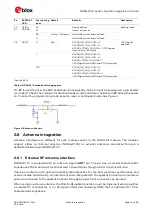
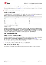
Pin
F7
is used to enter the ESP bootloader. Consequently, this pin must be exposed on a pin header
(or similar) to flash the module. To enter bootloader mode, hold down the Boot pin
F7
during the power
on. To enter the programming mode, assert a reset in bootloader mode. See
Figure 4: Button on Boot pin
2.6
Antenna integration
Antenna interfaces are different for each module variant in the NORA-W10 series. The modules
support either an internal antenna (NORA-W106) or external antennas connected through a
dedicated antenna pin (NORA-W101).
2.6.1
External RF antenna interface
NORA-W101 is equipped with an antenna signal (
ANT
) pin. The pin has a nominal characteristic
impedance of 50
and must be connected to the antenna through a 50
transmission line.
Choose an antenna with optimal radiating characteristics for the best electrical performance and
overall module functionality. An internal antenna, integrated on the application board or an external
antenna connected to the application board through a proper 50
connector, can be used.
When using an external antenna, the PCB-to-RF-cable transition must be implemented using either
a suitable 50
connector, or an RF-signal solder pad (including GND) that is optimized for 50
characteristic impedance.