


LILY-W1 series - System integration manual
UBX-15027600 - R09
System description
Page 10 of 64
C1 - Public
Function
Pin Name
Pin No. Power
Type
Signal Name
Remarks
USB_DM
24
VCC
DS
USB Differential Data -
Control
PD-n
14
VCC
I,PU
Power down
Active low
HOST_WKUP
19
VCC_IO O
Host Wake-Up
Module to Host
WAKE_UP
17
1.8V
(int.)
I,PU/PD Radio Wake-Up
Host to Module, programmable Pull
resistor.
1.8V CMOS input
USB/SDIO-n
22
1.8V
(int.)
I,PU
Host interface
selection
Low level activates the SDIO interface.
1.8V CMOS input
Radio
ANT
12
VCC
RF
Antenna signal
Only available in LILY-W131
ANT_SEL
15
VCC
O
Antenna diversity
selection
Only available on LILY-W131. Inverted
version of ANT_SEL-n
ANT_SEL-n
16
VCC
O
Antenna diversity
selection
Only available on LILY-W131. Inverted
version of ANT_SEL
Other
NC
18, 20
-
-
Reserved
Do not connect
Table 3: LILY-W1 module pin definition, grouped by function
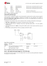
⚠
Do not apply any voltage to digital, control and radio signal groups while in Not Powered mode to
avoid damaging the module.
1.3
Supply interfaces
1.3.1
Main supply inputs
The power for the LILY-W1 series modules must be supplied via the
VCC
and
VCC_IO
pin. All supply
voltages used inside the modules are generated from the
VCC
through internal LDOs.
The current drawn by the LILY-W1 series through the
VCC
pins can vary by several orders of
magnitude depending on operation mode and state. It can change from the high current consumption
during Wi-Fi transmission at maximum RF power level in connected-mode, to the low current
consumption during low power idle-mode with the power saving configuration enabled.
Detailed description on the electrical requirements of the supply voltages can be found in the
LILY-W1 series Data Sheet [1]
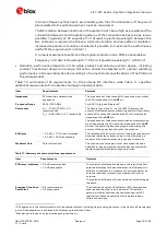
Rail
Allowable Ripple (peak to peak)
over DC supply
Current consumption, active
mode
Notes
10-100 kHz
100 kHz-1 MHz
>1 MHz
VCC
50
𝑚𝑚𝑚𝑚
𝑝𝑝𝑝𝑝−𝑝𝑝𝑝𝑝
40
𝑚𝑚𝑚𝑚
𝑝𝑝𝑝𝑝−𝑝𝑝𝑝𝑝
20
𝑚𝑚𝑚𝑚
𝑝𝑝𝑝𝑝−𝑝𝑝𝑝𝑝
340 mA
MCS0, +17 dBm
VCC_IO
50
𝑚𝑚𝑚𝑚
𝑝𝑝𝑝𝑝−𝑝𝑝𝑝𝑝
40
𝑚𝑚𝑚𝑚
𝑝𝑝𝑝𝑝−𝑝𝑝𝑝𝑝
20
𝑚𝑚𝑚𝑚
𝑝𝑝𝑝𝑝−𝑝𝑝𝑝𝑝
1.5 mA
Table 4: Summary of voltage supply requirements
The LILY-W1 series modules are powered by one of the following DC supplies:
•
Switching Mode Power Supply (SMPS)
•
Low Drop Out (LDO) regulator
The SMPS is the ideal choice when the available primary supply source has higher value than the
operating supply voltage of the LILY-W1 series modules. The use of SMPS provides the best power
efficiency for the overall application and minimizes current drawn from the main supply source.
1
When choosing SDIO bus for host communication, power consumption could be significantly lower compared to USB mode.
2
Ripple measured on u-blox EVK’s power connectors.