2
Qwik Install
STEP 1:
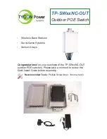
Install the POE switch into the housing leaving adequate room
for CAT5 cables. Velcro strips have been included for easy and secure
installation of the POE switch into the housing.
STEP 2:
Install the switch housing to a pole using the included U-bolts
or your supplied hose clamps. You can also mount to a wall using your
supplied screws. Always mount with the CAT5 cables exiting the bottom
of the unit to maintain weatherproofing. Tighten securely but don’t over-
do it and crack the housing.
STEP 3:
The switch can be powered via POE into the uplink port or
with a DC source connected to the switch green wire terminal connector
or both. So the switch can be powered with a primary and backup pow-
er source if desired. Whatever voltage is used to power the switch, that
is the same voltage that appears on the POE output ports.
STEP 4:
Route CAT5 cables thru the feedthroughs. Each feedthrough
can accommodate up to two CAT5 cables or DC Cable.
STEP 5:
Power up the switch by applying power via POE or DC con-
nector. Observe the LEDS for proper operation.
Link
(Green On)
Activity
(Green Blinking)
POE Detect
(Yellow On)
POE Detect Error
(Yellow Blinking)
Power On
(Green On)
Power On Alarm
(Red On)
STEP 6:
Do not rely on the RJ45 connectors to support the CAT5 cable
by itself. Add some strain relief inside the enclosure and outside the
enclosure. Inside the enclosure can use a simple tie-wrap around each
wire or group of wires so the weight of the wires outside the enclosure
aren’t pulling on the switch connectors. This will lead to failure over
time. Outside the enclosure tie wrap the cable bundle and attach to the
pole or mount to support the cable weight.
STEP 7:
Button it up by checking the rubber gasket is free from any
contamination then installing the cover and tightening the 4 screws.


