ENGLISH
FC430LPSB Loop Powered Addressable Sounder Base
FC430LPASB Loop Powered Addressable Sounder/Beacon Base
TECHNICAL SPECIFICATION
System Compatibility:
Use only with FireClass Fire Alarm Controllers
Environment:
Models for indoor use only
Operating Temperature:
-25°C to +70°C
Storage Temperature:
-40°C to +70°C
Operating Humidity:
Up to 95% (non-condensing)
Dimensions:
Height: 36.5 mm – Diameter: 115 mm
Weigth
Sounder only:
160g
Sounder/Beacon:
190g
Mounting Requirements:
Surface mount
The flat surface mounting flange is supplied with the base.
The mounting flange has to four drill positions for mounting holes at 50mm,
60mm, 70mm and 80mm. The sounder/sounder beacon body clips onto
the mounting flange.
Electrical Characteristics
Addressable Loop Voltage:
20 - 40Vdc
DC Loop Loading
Quiescent:
350µA
Alarm:
See table 1
EMC:
The base complies with the following:
Product family standard EN50130-4 in re-
spect of Conducted Disturbances, Radi-
ated Immunity, Electrostatic Discharge,
Fast Transients and Slow High Energy
EN61000-6-3 for Emissions.
Low/Mid Low
Mid High/High
Sound Output
60/70
80/90
dB
Sounder Only
2.6
4.4
mA
Sounder and Beacon 0.5Hz
5.7
7.5
mA
Sounder and Beacon 1Hz
6.8
8.6
mA
Tab. 1
FC430LPSB and FC430LPASB Current Draw
INTRODUCTION
The FC430LP Series of Loop Powered Addressable Sounder/Sounder-Beacons
are designed to be driven from an FireClass controller via the addressable loop.
Tone, volume and flash rates are set in FireClass Console.
FEATURES
The sounder has four volume settings ‘High’ (90dB ±3), ‘Mid High’ (80
±3dB), ‘Mid Low’ (70 ±3dB)or ‘Low’ (60dB ±3).
The beacon has two flash rates ‘Slow Flash’ (1/2Hz) or ‘Fast Flash’ (1Hz).
The FC430LP Series have a built-in line isolator.
IDENTIFICATION OF PARTS
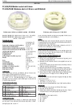
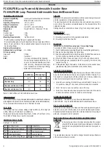
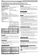
See Figs 1, 2, 3 and 5.
1
Locking Device
6
Cable Entry
2
Locking Device fits here
7
Sounder/Beacon Base
3
Programming Port
8
FireClass Detector
4
Electrical Backbox
9
Locking Device
5
Type A Mounting Flange
10
FireClass Controller
CABLING
Cables are to be selected in accordance with the system design document
and the requirements of the applicable standards.
The maximum section of the cable that can be connected at any one termi-
nal is 2.5mm
2
.The section is calculated based on the characteristics of the
cable and the load.
Cabling should be connected as shown in Fig. 5 ensuring correct polarity.
WIRING NOTES
The following notes apply:
1)
All wiring must conform to the applicable standards.
2)
All wiring must be free of earths.
MOUNTING
Installation to a flat surface using type ‘A’ mounting flange
To install an FC430LP base, proceed as follows:
1)
Feed the addressable loop wiring through the mounting flange cable entry.
2)
Secure the mounting flange to a flat surface.
3)
Feed the addressable loop wiring through the FC430LP base cable en-
try, then clip the sounder base to the mounting flange.
4)
Wire the FC430LP base as shown in Fig. 5 ensuring correct polarity.
5)
Fit the locking device (supplied) to the base, pressing it in until it is fully
seated. See Fig. 3.
6)
Fit the address flag to the detector. Fit the detector to the sounder base,
(the address flag will be transferred to the sounder base).
ADDRESS PROGRAMMING
The FC430LP devices have a default factory set address of 255, this must
be set to the loop address of the device using the FC490ST Service Tool.
The sounder is programmed with the address prior to being installed by
using the internal programming port (see Figs 1 and 4).
+
Note: When connecting FC430LP Bases to the FC490ST Service Tool,
it is possible a delay of 10 seconds until communication is possible.
+
Note: This device uses one address only on the loop.
+
Note: Once the address has been programmed, take note of the device
location and address number, to include on site drawings.
ORDERING INFORMATION
FC430LPSB:
Sounder only Loop Powered Addressable Base
FC430LPASB: Loop Powered Addressable Sounder/Beacon Base
RECYCLING INFORMATION
Customers are recommended to dispose of their used equipments (panels,
detectors, sirens, and other devices) in an environmentally sound manner.
Potential methods include reuse of parts or whole products and recycling of
products, components, and/or materials.
WASTE ELECTRICAL AND ELECTRONIC EQUIPMENT (WEEE)
DIRECTIVE
In the European Union, this label indicates that this product
should NOT be disposed of with household waste. It should be
deposited at an appropriate facility to enable recovery and re-
cycling.
The manufacturer reserves the right to change the technical specifications
of this product without prior notice.
2
Fixing instructions Doc. version 2.0 16 March 2012
FC430LP Series of Loop Powered Addressable Sounder/Sounder-Beacons
FireClass


