408–4047
PRO–CRIMPER II Hand Tool Assembly 58546–1
5 of 5
Rev D
7. MAINTENANCE AND INSPECTION
7.1. Maintenance
Ensure that the tool and dies are clean by wiping
them with a clean, soft cloth. Remove any debris with
a clean, soft brush. Do not use objects that could
damage the tool. When not in use, keep handles
closed to prevent objects from becoming lodged in
the crimping dies, and store in a clean, dry area.
7.2. Visual Inspection
The die assembly should be inspected on a regular
basis to ensure that they have not become worn or
damaged. Inspect the crimping chambers for
flattened, chipped, worn, or broken areas. If damage
or abnormal wear is evident, the tool or dies must be
replaced. See Section 8, REPLACEMENT.
8. REPLACEMENT
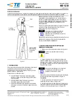
Customer–replaceable parts are shown in Figure 1.
Available separately, PRO–CRIMPER II Repair Kit
679221–1 includes a replacement nut and a variety of
pins, rings, screws, and springs. If the dies are
damaged or worn excessively, they must be replaced.
Order the repair kit and replaceable parts through
your Tyco Electronics Representative, or call
1–800–526–5142, or send a facsimile of your
purchase order to 717–986–7605, or write to:
CUSTOMER SERVICE (38–35)
TYCO ELECTRONICS CORPORATION
PO BOX 3608
HARRISBURG, PA 17105–3608
For tool repair service, please contact a Tyco
Electronics Representative at 1–800–526–5136.
9. STANDARD SOLISTRAND TERMINALS
To crimp standard SOLISTRAND terminals and
parallel splices, refer to Instruction Sheet 408–8678.
10. REVISION SUMMARY
Revisions to this instruction sheet per
EC 0990–1181–03 include:
S
Updated document to corporate requirements
S
Added markings to dies in Figure 2
S
Changed wire size range from 22–16 to 22–18
in table in Figure 5


