


408-1537
Hand Tool Assembly 59282
3 of 4
Rev B
Tyco Electronics Corporation
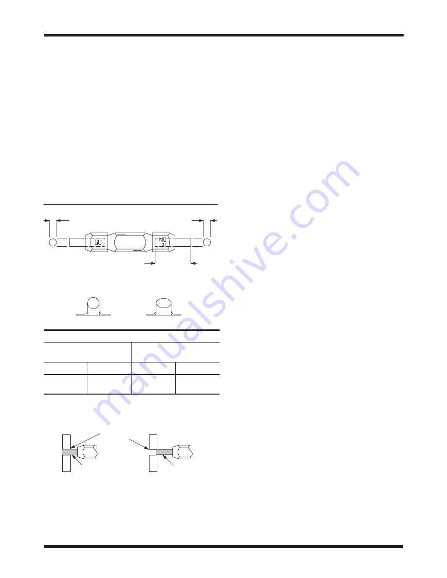
straight into the chamber, but do not force it. The
GO element must pass completely through the
chamber.
5. Align the NO–GO element and try to insert it
straight into the same crimping chamber section.
The NO–GO element may begin entry as shown in
Figure 4, but must not pass through the chamber.
If the crimping chamber conforms to the gage
inspection, the tool may be considered dimensionally
correct and should be lubricated with a THIN coat of
any good SAE 20 motor oil. If the crimping chamber
does NOT conform to the gage inspection, the tool
must be returned for further evaluation and repair.
See Section 5, REPLACEMENT AND REPAIR.
For additional information regarding the use of a plug
gage, refer to Instruction Sheet 408–7424.
NO-GO Diameter
GO Diameter
Suggested Plug Gage Design
50.8 [2.0] Min Typ
Die Closure Configuration
Insulation Barrel Crimp
Wire Barrel Crimp
GAGE ELEMENT DIAMETER
Insulation Barrel Section of
Crimping Chamber
Wire Barrel Section of
Crimping Chamber
GO
NO-GO
GO
NO-GO
4.064-4.072
[.1600-.1603]
4.265-4.267
[.1679-.1680]
3.353-3.360
[.1320-.1323]
3.503-3.505
[.1379-.1380]
Figure 5
ÉÉ
ÉÉ
ÉÉ
ÉÉ
ÉÉ
ÉÉ
É
É
É
É
É
É
GO Element
NO-GO Element
GO element must pass
completely through the
crimping chamber.
NO-GO element may enter
partially, but must not pass
completely through the
crimping chamber.
Crimping
Chamber
Inspection of Crimping Chamber
4.3. CERTI-CRIMP Hand Tool Ratchet Control
Inspection
Check the ratchet to ensure that the ratchet does not
release prematurely, allowing the dies to open before
they have fully bottomed. Proceed as follows:
1. Remove traces of oil or dirt from the bottoming
surfaces of the dies.
2. Obtain a 0.025 mm [.001 in.] shim that is
suitable for checking the clearance between the
bottoming surfaces of the dies.
3. Select a splice and
maximum size wire for the
splice.
4. Position the splice in the crimping chamber
according to Section 3, CRIMPING PROCEDURE.
Holding the wire in place, squeeze the tool handles
together until the ratchet releases. Hold the tool
handles in this position, maintaining just enough
pressure to keep the dies closed.
5. Check the clearance between the bottoming
surfaces of the dies. If the clearance is 0.025 mm
[.001 in.] or less, the ratchet is satisfactory. If
clearance exceeds 0.025 mm [.001 in.], the ratchet
is out of adjustment and must be repaired. See
Section 5, REPLACEMENT AND REPAIR.
5. REPLACEMENT AND REPAIR
Customer–replaceable parts are listed in Figure 6.
A complete inventory should be stocked and
controlled to prevent lost time when replacement of
parts is necessary. Parts other than those listed
should be replaced by Tyco Electronics to ensure
quality and reliability. Order replacement parts
through your Tyco Electronics Representative, or call
1–800–526–5142, or send a facsimile of your
purchase order to 717–986–7605, or write to:
CUSTOMER SERVICE (038–035)
TYCO ELECTRONICS CORPORATION
PO BOX 3608
HARRISBURG PA 17105–3608
For customer repair service, contact a Tyco
Electronics Representative at 1–800–526–5136.
6. REVISION SUMMARY
S
Updated document to corporate requirements
S
Changed dimensions in table in Figure 5


