TYAN Transport TA26-B3892 Скачать руководство пользователя страница 37

Chapter 2: Setting Up

27

2.2.4 Installing PCI Cards

The TA26-B3892 has six PCI card slots:

1 x PCI card slot
2 x PCI-E card slots
3 x PCI-X card slots

Follow these instructions to install any of the above kinds of 
PCI cards.

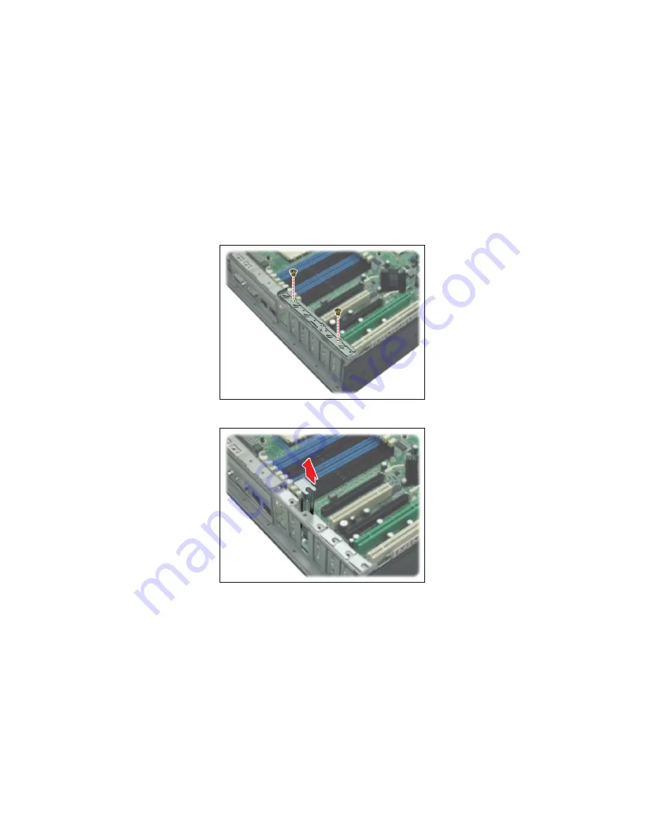
1. Unscrew the bracket covering the PCI card slots as 

shown.

2. Lift up the card slot cover.

3. Insert the PCI card into the appropriate slot. Replace the 

bracket covering the PCI card slots.

Содержание Transport TA26-B3892

Страница 1: ...Tyan Transport TA26 B3892 High Performance Barebone System Service Engineer s Manual...

Страница 2: ......

Страница 3: ...egin 15 2 0 2 Work Area 15 2 0 3 Tools 15 2 0 4 Precautions 16 2 1 Rack Mounting 17 2 1 1 Installing the Server in a Rack 17 2 2 Installing Motherboard Components 22 2 2 1 Removing the Chassis Cover 2...

Страница 4: ...placing the Backplane 46 3 7 1 Backplane Features for TA26 B3892 48 3 7 2 System Fan Layout 50 3 7 3 Backplane Connector Pin Definitions 51 3 8 Replacing the Power Supply 55 3 8 1 Standard Power Suppl...

Страница 5: ...to product descriptions and or specifications at any time without notice In no event will TYAN be held liable for any direct or indirect incidental or consequential damage loss of use loss of data or...

Страница 6: ...ent into an outlet on a circuit different from that of the receiver Consult the dealer on an experienced radio television technician for help Notice for Canada This apparatus complies with the Class B...

Страница 7: ...nents and provides block diagrams of the system Chapter 2 Covers procedures on installing the CPU mem ory modules and hard drives Chapter 3 Covers removal and replacement procedures for pre installed...

Страница 8: ...his pin If your outlet does not support this kind of plug contact your electrician to replace your obsolete outlet Do not place anything on the power cord Place the power cord where it will not be in...

Страница 9: ...high bandwidth memory design and a lightning fast PCI X bus implementation The TransportTM TA26 B3892 not only empowers your company in today s demanding IT environ ment but also offers a smooth path...

Страница 10: ...2 Chapter 1 Overview 1 2 Product Models Model HDD Bays HDD Backplane Power Supply B3892T26V8H 8 8 port SAS SATA Single 600W B3892T26V8HR 8 8 port SAS SATA 600W 1 1 redundant...

Страница 11: ...rect 48 bit LBA support Expansion Slots Two 2 PCI Express x16 slots each w x8 signal Two 2 PCI X 133 100 MHz slots One 1 PCI X 100 MHz slot One 1 PCI 32 bit 33 MHz v2 3 compliant slot Supports a total...

Страница 12: ...r Management TSM Optional TYAN SMDC M3291 IPMI v2 0 compliant remote server man agement kit Power Supply EPS 12V 2U 600W with PFC for B3892T26V8H EPS 12V 2U 600W 1 1 redundant power with PFC for B3892...

Страница 13: ...nts Component Description Industry standard 2U chassis 8 hot swap HDD bays Tyan Thunder K8HM S3892G3NR mother board pre installed Slim DVD ROM drive pre installed LED and USB control board pre install...

Страница 14: ...to TYAN s Web site for service http www tyan com The Web site also provides information on other TYAN prod ucts plus FAQs compatibility lists BIOS settings and more 1 x Tyan Driver CD Power Cables Lef...

Страница 15: ...Chapter 1 Overview 7 Screw Pack Sliding Rail Brackets FDD Power Cable SAS Cable...

Страница 16: ...up B3892T26V8H is also available In both cases the output voltage is the same Reset switch USB ports Warning LED HDD activity LED LAN LEDs Hard Drive Bay x 8 DVD ROM drive HDD Tray Activity LEDs Power...

Страница 17: ...LAN2 LAN3 Linkage Green Green OFF ON Blinking OFF LAN linked LAN accessing No LAN linked Fail Red OFF ON OFF System fails Normal Hot Swappable HDD Tray Power LED Green OFF ON OFF Power connected Powe...

Страница 18: ...ft Side Green Green OFF ON Blinking OFF 10Mb 100Mb linked 10Mb 100Mb activity No LAN linked RJ45 NIC3 Linkage Activty Right Side Green ON 100Mb linked and activity Zippy Power Supply LED Green Green A...

Страница 19: ...Chapter 1 Overview 11 1 5 4 Motherboard Layout...

Страница 20: ...r JP1 JP2 SMDC ASF2 0 Select Jumper Close 1 2 Default supports ASF 2 0 Close 2 3 supports SMDC card JP3 VGA Enable Disable Jumper Close 1 2 Default enabled Close 2 3 Disabled JP4 LAN3 Enable Disable J...

Страница 21: ...Chapter 1 Overview 13 1 5 6 System Block Diagram...

Страница 22: ...Supply 5 CPU1 6 CPU1 Memory Slots 7 SATA SAS Backplane 8 LED Control Board Cable 9 Eight 8 SATA SAS HDDs 10 DVD ROM Cable 11 System Fans 12 SATA SAS Cables 4 13 PCIX P1 Slot 14 PCIX S2 Slot 15 PCIX S...

Страница 23: ...NOTE...

Страница 24: ...16 Chapter 1 Overview...

Страница 25: ...ntainers to keep small components separated Putting all small components in separate containers prevents them from becoming lost Adequate lighting and proper tools can prevent you from accidentally da...

Страница 26: ...dy of any other grounded appliance Avoid touching motherboard components IC chips connectors memory modules and leads The motherboard is pre installed in the system When removing the motherboard alway...

Страница 27: ...rackets x 4 2 1 1 Installing the Server in a Rack Follow these instructions to mount the TA26 B3892 into an industry standard 19 rack NOTE Before mounting the Transport TA26 B3892 in a rack ensure tha...

Страница 28: ...es to each side of TA26 B3892 as shown using two 2 M4L6 S10C screws A from the supplied screws kit 2 Attach the inner rails both sides of the unit using nine 9 M4 L5 screws C on each side Installing O...

Страница 29: ...Chapter 2 Setting Up 19 2 Secure the outer rail to the rack using 2 brackets and M6 screws B for each side Secure the mounting brack ets from inside not outside of the rack...

Страница 30: ...er 2 Setting Up Rackmounting the Server 1 Draw out the middle rail to the latch position 2 Lift the unit and then insert the inner slide rails into the middle rails 3 Push the unit in and press the la...

Страница 31: ...h the whole system into the rack 5 Secure the mounting handles of the unit to the rack Note To avoid injury it is strongly recom mended that two people lift the TA26 B3892 into the place while a third...

Страница 32: ...all components on to the motherboard including CPU memory modules and PCI card 2 2 1 Removing the Chassis Cover Follow these instructions to remove the Transport TA26 B3892 chassis cover 1 Turn the sc...

Страница 33: ...lling the CPU Follow these instructions to install the CPU 1 Lift up the CPU lever to unlock the socket 2 Place the CPU in the CPU socket ensuring that pin 1 is located as shown below 3 Press the CPU...

Страница 34: ...ng Up 4 Place the fan and heatsink on top of the CPU and attach with two screws as shown below 5 Attach the fan power cable to the connector on the motherboard as shown 6 Repeat these steps when insta...

Страница 35: ...rd 2 Press the memory slot locking levers in the direction of the arrows as shown below 3 Align the memory module with the slot The module has indentations that align with notches in the slots 4 Inser...

Страница 36: ...5 6 7 8 CPU1_DIMMA0 X X X X X X CPU1_DIMMB0 X X X X X X CPU1_DIMMA1 X X X X X X CPU1_DIMMB1 X X X X X X CPU1_DIMMA2 X X X X CPU1_DIMMB2 X X X X CPU1_DIMMA3 X X X X CPU1_DIMMB3 X X X X CPU2_DIMMA0 X X...

Страница 37: ...lot 2 x PCI E card slots 3 x PCI X card slots Follow these instructions to install any of the above kinds of PCI cards 1 Unscrew the bracket covering the PCI card slots as shown 2 Lift up the card slo...

Страница 38: ...892 supports up to eight serial SATA hard drives Follow these instructions to install a hard drive 1 Press the locking lever latch in the direction shown by the arrow below The latch will pop open 2 S...

Страница 39: ...Chapter 2 Setting Up 29 4 Remove the base 5 Place a hard drive into the drive tray 6 Screw the hard drive in place using 4 HDD screws...

Страница 40: ...30 Chapter 2 Setting Up 7 Reinsert the tray into the bay and press the locking lever to secure...

Страница 41: ...ructions to install a floppy disk drive in the TA26 B3892 1 Remove the top left hand drive tray from the TA26 B3892 as shown Note The top left hand drive bay is the only bay that can accomodate a flop...

Страница 42: ...he floppy disk drive from the front 3 Plug the floppy disk drive cable into the port on the back of the floppy disk drive Thread the cable out through the back of the empty drive bay 4 Slide the flopp...

Страница 43: ...Chapter 2 Setting Up 33 Note To release the floppy disk drive from the drive bay you will need to press the release catch inside the chassis...

Страница 44: ......

Страница 45: ...malfunc tions Use containers to keep small components separated Putting all small components in separate containers keeps them from becoming lost Adequate lighting and proper tools can prevent you fro...

Страница 46: ...metal body of any other grounded appli ance Avoid touching motherboard components IC chips connectors memory modules and leads The motherboard is pre installed in the system When removing the motherb...

Страница 47: ...ssembly Flowchart The following flowchart outlines the disassembly procedure Rear Components Chassis top cover Mainboard DIMMs CPU heatsink assembly PCI card Mainboard Power supply Front Components FA...

Страница 48: ...over Before replacing any parts you must remove the chassis cover Follow these instructions to remove the cover of the Transport TA26 B3892 chassis cover 1 Remove the screw on the back side Then slide...

Страница 49: ...otherboard Cables Before replacing the motherboard or certain components remove cables connected to the motherboard Follow these instructions to remove all motherboard cabling 1 Disconnect power cable...

Страница 50: ...40 Chapter 3 Replacing Pre Installed Components 3 Disconnect the three fan power cables...

Страница 51: ...ts 41 3 4 2 Removing the Motherboard After removing all of the aforementioned cables follow these instructions to remove the motherboard from the chassis 1 Remove the ten screws securing the motherboa...

Страница 52: ...the Slim DVD ROM Follow these instructions to replace the DVD ROM 1 Remove the power data cable from the rear of the DVD ROM drive 2 Press the tab in the direction shown to release the DVD ROM drive...

Страница 53: ...ents 43 4 Remove the two screws that secure DVD ROM drive to the bracket 5 Replace the DVD ROM drive 6 Secure the DVD ROM to the bracket using two screws Then replace the unit into the drive bay and c...

Страница 54: ...ED Control Board Follow these instructions to replace the LED control board 1 Remove the screw securing the LED control board unit to the chassis 2 Remove the connector cables from the backplane 3 Sli...

Страница 55: ...om the LED control board USB adapter board 5 Remove the five screws securing the LED control board USB adapter board to the bracket 6 Release the LED control board USB adapter board from bracket After...

Страница 56: ...ckplane 1 Remove all of cables connected to the backplane includ ing fan cables DVD ROM cable Control board cable USB cable front panel LED cable power cables and SATA cables Power cable USB Cable Con...

Страница 57: ...Chapter 3 Replacing Pre Installed Components 47 2 Remove the ten screws to release the backplane 3 Turn the locking keys at the base of the backplane 4 Pull out the backplane...

Страница 58: ...48 Chapter 3 Replacing Pre Installed Components 3 7 1 Backplane Features for TA26 B3892 Front View...

Страница 59: ...Chapter 3 Replacing Pre Installed Components 49 Rear View...

Страница 60: ...re provides the information for system fan layout Refer to the tables on p 48 for information on connec tion System Fan Monitoring Signal Barebone System Fan Connect to Motherboard Fan Fan 1 FAN1 J51...

Страница 61: ...AN2 GR LED 6 LAN2 LED 7 LAN2 GR LED 8 LAN2 LED 9 LAN3 GR LED 10 LAN3 LED 11 LAN3 GR LED 12 LAN3 LED 13 None 14 None 15 System HDD LED 16 System HDD LED 17 System power LED 18 System power LED 19 Syste...

Страница 62: ...ght be different from the system fan name FAN1 4 CPUFAN1 4 4 pin Fan Connector with Speed Control FAN5 FAN6 4 pin Fan Connector 19 GND 20 VCC 21 DMARQ 22 VCC 23 DIOW 24 VCC 25 DIOR 26 VCC 27 IORDY 28...

Страница 63: ...P pin out J4 J5 USB pin out JP4 power small 4 P pin out JP5 LED pin out 1 GND 2 12V 3 Clock 4 PWM 1 12V 2 GND 3 GND 4 5V 1 USB1 power 2 USB2 power 3 USB1 DATA 4 USB2 DATA 5 USB1 DATA 6 USB2 DATA 7 US...

Страница 64: ...9 PLED3 10 GND 11 ALED3 12 ALED3 13 None 14 Key 1 PLED4 2 GND 3 ALED4 4 ALED4 5 PLED5 6 GND 7 ALED5 8 ALED5 9 None 10 Key 1 PLED6 2 GND 3 ALED6 4 ALED6 5 PLED7 6 GND 7 ALED7 8 ALED7 9 PLED8 10 GND 11...

Страница 65: ...y in your TA26 B3892 system 3 8 1 Standard Power Supply 1 Remove the chassis cover See Removing the Cover on page 38 for more details 2 Detach the power cables from the motherboard and backplane See D...

Страница 66: ...If the optional 1 1 redundant power supply is fitted either of the two units can be hot swapped Follow these instructions to replace a single power unit with a redundant power supply unit Note Before...

Страница 67: ...2 Remove the screws which fix the bracket to the sides of the redundant power supply casing 3 Screw the bracket to the rear of the power supply casing 4 Insert the redundant power supply casing into...

Страница 68: ...Replacing Pre Installed Components 5 Screw the casing to the chassis exterior 6 Screw the casing to the chassis interior 7 Fix the redundant power supply switch to the chassis rear window with two Hex...

Страница 69: ...hapter 3 Replacing Pre Installed Components 59 8 Insert the new power supply unit and secure by turning the locking screw 9 Re attach all power supply connector cables to the moth erboard and backplan...

Страница 70: ......

Страница 71: ...t 3Pin FAN Auto FAN1 2 Power Con trol Disabled Auto FAN Power Control Enabled PWM Minimal Duty Cycle 50 Duty Cycle PWM Minimal Duty Cycle 30 Duty Cycle Auto FAN3 4 Power Con trol Disabled PWM Minimal...

Страница 72: ...ard J16 SAS Channel SATA0 SATA1 SATA2 SATA3 Table 2 System Fan to Motherboard System Fan Connects to Motherboard Fan 1 FAN1 Fan 2 FAN2 Fan 3 FAN3 CPU Fan 1 CPUFAN1 CPU Fan 2 CPUFAN2 Table 3 Power Supp...

Страница 73: ...lane Power Supply Connects to Backplane P3 4 pin power cable J1 4 pin connector P3 4 pin power cable J2 4 pin connector P3 4 pin power cable J3 4 pin connector Backplane Connects to Motherboard JP3 TO...

Страница 74: ......

Страница 75: ...cess resources such as in depth Linux Online Support sections with downloadable Linux drivers and comprehensive compatibility reports for chassis memory and much more With all these convenient resourc...

Страница 76: ...re due to the alteration mis use abuse or improper maintenance of products NOTE A receipt or copy of your invoice marked with the date of purchase is required before any warranty service can be render...

Отзывы: