Appendix II: Cable Connection Tables
SAS/SATA Cables
Table 1: B4987G26W3H/B4987G26W3HI
M1221
Connect to
Motherboard
J1 Connector
→
SAS 4
J2 Connector
→
SAS 5
J3 Connector
→
SAS 6
Power Cables
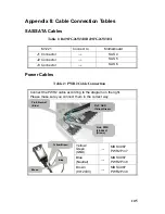
Table 2: PWR2 Cable Connection
Connect the PWR2 cable according to the diagram on the right.
Please make sure you connect them in the correct way.
Yellow/
Green
(GND)
→
MB S4987
PWR2 Pin7
Blue
(Neutral)
→
MB S4987
PWR2 Pin8
Brown
(90~240V)
→
MB S4987
PWR2 Pin9
Pin8: Neutral
(Blue)
Pin7: GND
(Yellow/Green)
Pin9: PWR
(90~264V)
(Brown)
Yellow/Green
Blue
Brown
105
Содержание Transport GT26-B4987
Страница 1: ...Transport GT26 B4987 Service Engineer s Manual ...
Страница 2: ......
Страница 27: ...1 5 6 System Block Diagram Chapter 1 Product Overview 19 ...
Страница 62: ...3 6 1 M1003 LED Control Board Features 54 Chapter 3 Replacing Pre Installed Components ...
Страница 119: ...The following diagrams may guide you how to install the InfiniBand Driver Welcome Screen License Agreement 111 ...
Страница 120: ...Registration Info Install Path SDP WSD Activation 112 ...
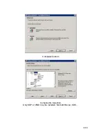
Страница 121: ...Complete Custom Components Selection Only SDP or WSD may be installed Not both Below SDK 113 ...
Страница 122: ...SDP WSD Activation The installer installs 3 types of devices InfiniBand Fabric HCA IPoIB Interface 114 ...


