30
2.8 -
Installing Add-In Cards
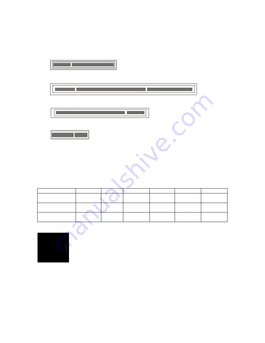
Before installing add-in cards, it’s helpful to know if they are fully compatible
with your motherboard. For this reason, we’ve provided the diagrams below,
showing the slots that appear on your motherboard.
PC I-X (64/ 133)
PCI Express x8 Slot
PCI Slot
PC I Expr es s (x4) Slot
Simply find the appropriate slot for your add-in card and insert the card
firmly. Do not force any add-in cards into any slots if they do not seat in
place. It is better to try another slot or return the faulty card rather than
damaging both the motherboard and the add-in card.
PCI IDESELs and IRQ Assignments
Slot or Device
IDSEL#
Bus#
PIRQ
PIRQ
PIRQ
PIRQ
PCI –X P1 +
PCI-E 1
AD19 PCI-X
Bus
INT_0 INT_1 INT_2 INT_3
PCI Slot #2
(32bit)
AD16 PCI
Bus
INT_A INT_B INT_C INT_D
Onboard
XG20
AD17 PCI
Bus
INT_B
NOTE
YOU MUST ALWAYS
unplug the power connector from the
motherboard before performing system hardware changes.
Otherwise you may damage the board and/or expansion
device.
Содержание Tempest i5000VS S5372
Страница 4: ...4...
Страница 8: ...8 NOTE...
Страница 11: ...11 2 2 Block Diagram Tempest i5000VS S5372 Block Diagram...
Страница 16: ...16 JP1 IPMB Connector 1 Pin 1 IPMB DATA Pin 2 GND Pin 3 IPMB CLK Pin 4 NC JP4 CN15 JP1 CN12...
Страница 18: ...18 JP2 JP3 SMDC ASF1 0 Select Header 1 3 Support ASF1 0 3 1 Support SMDC card CN11 CN19 CN20 CN21 JP2 JP3...


