background image

Chapter 1: Overview

7

1.4

About the Product

This section contains the hardware diagrams and a block 
diagram of the GT24 system.

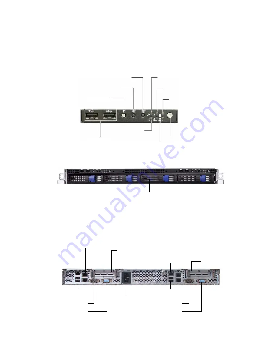
1.4.1 System Front View

1.4.2 System Rear View

HDD activity LED

Power switch

Power LED

Reset switch

USB ports

Warning LED

2 x LAN LEDs

ID Switch

NMI switch

ID LED

Hard Drive Bay x 4

Power Supply 
Socket

PCI-E Slot

Serial Port

VGA Port

LAN Port (NIC2)

IPMI (LAN)

2 USB ports

LAN Port (NIC1)

PCI-E Slot

LAN Port (NIC2)

LAN Port (NIC1)

Serial Port

VGA Port

2 USB ports

IPMI (LAN)

Содержание Tank GT24 (B5377) Service

Страница 1: ...Tank GT24 B5377 Service Engineer s Manual...

Страница 2: ......

Страница 3: ...descriptions and or specifications at any time without notice In no event will TYAN be held liable for any direct or indirect incidental or consequential damage loss of use loss of data or other mala...

Страница 4: ...ent into an outlet on a circuit different from that of the receiver Consult the dealer on an experienced radio television technician for help Notice for Canada This apparatus complies with the Class B...

Страница 5: ...Chapter 2 Covers procedures on installing the CPU mem ory modules an optional PCI card and hard drives Chapter 3 Covers removal and replacement procedures for pre installed components Appendix Descri...

Страница 6: ...is pin If your outlet does not support this kind of plug contact your electrician to replace your obsolete outlet Do not place anything on the power cord Place the power cord where it will not be in t...

Страница 7: ...2 1 Rack Mounting 15 2 1 1Installing the Server in a Rack 15 2 2 Installing Motherboard Components 20 2 2 1Removing the Chassis Cover 20 2 2 2Installing the CPU and Heatsink 21 2 2 3Installing the Mem...

Страница 8: ...e 43 3 6 1SAS SATA Backplane M1228 Features 45 3 7 Replacing the Cooling Fans 47 3 8 Replacing the Power Supply 48 3 8 1Replacing the Power Board 48 3 8 2Replacing the Power Supply 49 Appendix I BIOS...

Страница 9: ...kTM GT24 B5377 server system is capable of offering scalable 32 and 64 bit computing high bandwidth memory design The TYAN TankTM GT24 B5377 not only empowers your company in today s demanding IT envi...

Страница 10: ...onnectors One 9 pin COM port One 15 pin VGA port Front Panel Features Per node I O 2 USB 2 0 ports 1 eSATA port Optional LED indicators Power LED 2 LAN LEDs ID LED HDD active LED Warning LED Switches...

Страница 11: ...h fan speed monitor control 2 Passive CPU heatsinks Power Supply High efficiency EPS 12V 1U 600W with PFC Note put on the middle of the chassis 100V 240V AC input Regulatory FCC Class A Declaration of...

Страница 12: ...ponents are present and undamaged 1 3 1 Box Contents Component Description Industry standard 1U chassis 4 swappable HDD bays TYAN S5377 Tempest i5100T motherboard pre installed M1228 SAS SATA backplan...

Страница 13: ...to TYAN s Web site for service http www tyan com The Web site also provides information on other TYAN prod ucts plus FAQs compatibility lists BIOS settings and more 1 x Tyan driver CD Power Cords Lef...

Страница 14: ...6 Chapter 1 Overview Rail Kit Mounting Brackets x 4 Screws Kit Front Rear Sliding Brackets Front L Bracket x 2 Rear L Bracket x 2 Sliding Rails x 2...

Страница 15: ...View 1 4 2 System Rear View HDD activity LED Power switch Power LED Reset switch USB ports Warning LED 2 x LAN LEDs ID Switch NMI switch ID LED Hard Drive Bay x 4 PowerSupply Socket PCI E Slot Serial...

Страница 16: ...FF Random Blinking OFF HDD access activity No disk activity Hot Swappable SAS HDD Access LED Amber Amber OFF ON Random Blinking OFF HDD ready HDD access activity HDD not ready ID LED Blue OFF ON OFF S...

Страница 17: ...6 8 1 600W Power Supply 2 PCI E x16 Slot with riser card M2087 R 3 Memory Slots 4 Power Board Cover 5 CPU Socket 6 System Fans From right to left Fan1 Fan2 Fan3 and Fan4 7 PSU System Fans 8 SAS SATA B...

Страница 18: ...33 ECC 4 CH0 CH1 SATA 4 USB 2 0 6 2 REAR 2FRONT 2DOM PCI 32bit 33 VGA CHIP XGI 21 FRAME BUFFER MEM XGI 32M BYTES VGA CONNECTOR LPC SIO W83627DHG FWH OPMA Slot M3296 DMI RJ 45 HWM W83793G W PECI CK505...

Страница 19: ...Chapter 1 Overview 11 1 4 6 S5377 Board Parts Jumpers and Connectors...

Страница 20: ...onnector with Speed Control Pin Signal Pin Signal 1 HD_LED 2 HD_LED 3 RESET 4 RESET 5 PWR_LED 6 PWR_LED 7 WLED 8 WLED 9 SMBDAT 10 SMBCLK 11 EXT_INT 12 5V 13 5VSB 14 INTRUDER_N 15 PWR_SW 16 PWR_SW 17 L...

Страница 21: ...ntainers to keep small components separated Putting all small components in separate containers prevents them from becoming lost Adequate lighting and proper tools can prevent you from accidentally da...

Страница 22: ...y other grounded appliance Avoid touching motherboard components IC chips connectors memory modules and leads The motherboard is pre installed in the system When removing the motherboard always place...

Страница 23: ...Front x 2 Rear x 2 Mounting Ears including screws x 2 Screws Kit x 1 Mounting Brackets x 4 2 1 1 Installing the Server in a Rack Follow these instructions to mount the GT24 into an industry standard...

Страница 24: ...ng 2 screws from the supplied screws kit 2 Draw out the inner rails from rail assembly Install inner rails to left and right sides of chassis using 1 M4 4L A screw for each side Installing Outer Rails...

Страница 25: ...s 6 Reserve the distance same as in Step 2 on rear bracket Secure the rear bracket to outer rail with 2 M4 4L A screws 7 Secure the outer rail to the rack using 2 brackets and 4 M5 8L B screws for eac...

Страница 26: ...the Server 8 Draw out the middle rail to the latch position 9 Lift the chassis and then insert the inner slide rails into the middle rails 10 Push the chassis in and press the latch key A Then push t...

Страница 27: ...Up 19 11 Secure the mounting ears of chassis to the rack with 2 M5 15L C screws NOTE To avoid injury it is strongly recommended that two people lift the GT24 into the place while a third person screw...

Страница 28: ...install components on to the motherboard including CPU memory modules and PCI card 2 2 1 Removing the Chassis Cover Follow these instructions to remove the GT24 chassis cover 1 Release the screw on th...

Страница 29: ...g Up 21 2 2 2 Installing the CPU and Heatsink Follow these instructions to install the CPU and CPU heatsink 1 Locate the CPU sockets 2 Take off the CPU protection cap 3 Pull the CPU lever up to unlock...

Страница 30: ...2 Setting Up 4 Open the socket in the direction as shown 5 Place the CPU in the CPU socket ensuring that pin 1 is located as shown below 6 Close the socket and press the CPU socket lever down to secu...

Страница 31: ...Chapter 2 Setting Up 23 7 Place the heatsink on top of the CPU and screw into place as shown 8 Repeat the same procedures to install CPU and heatsink for the other CPU socket if necessary...

Страница 32: ...3 memory modules are sup ported All installed memory will automatically be detected and no jumpers or settings need to be changed The Tempest i5100T S5377 supports up to 32GB of memory All memory must...

Страница 33: ...at align with notches in the slots 4 Insert the memory module into the slot as shown 5 When inserted properly the memory slot locking levers lock automatically onto the indentations at the ends of the...

Страница 34: ...MM7 DIMM5 DIMM3 DIMM1 Four DIMMs per Channel 1 Empty Empty Empty Single Rank Empty Empty Single Rank Single Rank Empty Single Rank Single Rank Single Rank Single Rank Single Rank Single Rank Single Ra...

Страница 35: ...4 B5377 has two PCI E card slots with pre installed risers Follow these instructions for the PCI E card installation in your system 1 Locate the pre installed PCI E riser brackets 2 Remove the three s...

Страница 36: ...28 Chapter 2 Setting Up 4 Remove the screw securing the metal plate and remove it as shown 5 Insert a PCI E card into the pre installed PCI E riser as shown...

Страница 37: ...ng Up 29 6 Place back the riser assembly in the PCI E slot as shown 7 Secure the riser bracket in place with three screws 8 Repeat the same procedures to install the PCI E card for the other PCI E ris...

Страница 38: ...he GT24 chassis supports external SATA hard drives Follow these instructions to install an external SATA hard drive 1 Press the locking lever latch in the direction of arrow A and then pull the lockin...

Страница 39: ...lace a hard drive into the drive tray 6 Use 4 screws to secure the Hard Disk Drive NOTE The new HDD tray is compatible only with B5377 and models developed later The new sliding rails on both sides of...

Страница 40: ...2 Chapter 2 Setting Up 7 Reinsert the drive tray into the chassis A ensuring that the drive tray is completely inserted into the chassis B 8 Pressing the locking lever to secure the hard drive tray A...

Страница 41: ...lfunc tions Use containers to keep small components separated Putting all small components in separate containers keeps them from becoming lost Adequate lighting and proper tools can prevent you from...

Страница 42: ...body of any other grounded appli ance Avoid touching motherboard components IC chips connectors memory modules and leads The motherboard is pre installed in the system When removing the motherboard a...

Страница 43: ...Disassembly Flowchart The following flowchart outlines the disassembly procedure Rear Components Chassis cover Mainboard DIMMs CPU heatsink assembly PCI card Mainboard Power supply Front Components FA...

Страница 44: ...e Cover Before replacing any parts you must remove the chassis cover Follow these instructions to remove the cover of the Tank GT24 chassis cover 1 Release the screw on the back side Then slide the ch...

Страница 45: ...bles connected to the motherboard Follow these instructions to remove all motherboard cabling 1 Disconnect the ATX power and the TYFP3 cables and fan cables 2 Disconnect the SAS SATA hard drive cables...

Страница 46: ...After removing all the cables from the motherboard follow these instructions to remove the motherboard from the chassis 1 Remove the six screws securing each motherboard to the chassis 2 Remove the mo...

Страница 47: ...he LED Control Board Follow these instructions to replace the LED control board 1 Remove the five screws securing the front chassis cover 2 Turn over the front chassis cover in the direction of arrow...

Страница 48: ...pective connectors 5 Remove the three screws securing the LED control board to the front chassis cover 6 Lift the LED control board free from the front cover chas sis After replacement insert the unit...

Страница 49: ...Chapter 3 Replacing Pre Installed Components 41 3 5 1 M1003 LED Control Board Features J1 USB Connector J2 Front Panel Connector...

Страница 50: ...VCC5 2 VCC5 3 USB1 4 USB0 5 USB1 6 USB0 7 GND 8 GND 9 KEY PIN 10 GND 1 HDLED 2 HDLED 3 RESET 4 RESET 5 PW_LED 6 PW_LED 7 WLED 8 WLED 9 ICH_SMBDAT 10 ICH_SMBCLK 11 EXT_INT 12 VOLTAGE5 13 V5SB 14 INTRU...

Страница 51: ...plane 1 Remove all the connected cables from the SAS SATA backplane 2 Remove the three screws securing the SAS SATA back plane to the chassis 3 Grab the two labels to lift the SAS SATA backplane off U...

Страница 52: ...Installed Components 4 Remove the ten screws that secure the bracket to the SAS SATA backplane 5 Release the SAS SATA backplane free from the bracket 6 Replace the unit to the chassis following the ab...

Страница 53: ...Pre Installed Components 45 3 6 1 SAS SATA Backplane M1228 Features U4 SAS SATA4 U3 SAS SATA3 U2 SAS SATA2 U1 SAS SATA 1 Right HDD Power Access Left HDD Fail Connector Connector Connector Connector L...

Страница 54: ...46 Chapter 3 Replacing Pre Installed Components PW2 Power Connector J5 SAS SATA 4 J3 SAS SATA 3 J2 SAS SATA 2 J1 SAS SATA 1 PW1 Power Connector Connector Connector Connector Connector...

Страница 55: ...replace the cooling fans in your GT24 B5377 system 1 Remove the eight fan connectors from the motherboard 2 Remove the fan unit from the chassis 3 Remove the fan you want to replace in the direction o...

Страница 56: ...wer board and power supply in your GT24 B5377 system 3 8 1 Replacing the Power Board 1 Remove the screw securing the power board cover 2 Lift up the power board cover as shown 3 Disconnect all the ATX...

Страница 57: ...r board free from the chassis 5 Replace a new power board into the chassis following the above steps in reverse 3 8 2 Replacing the Power Supply To replace the power supply remove the power cover as d...

Страница 58: ...and PW2 connectors Remove the two screws that secure the power supply to the chassis 3 Lift the power supply free from the chassis 4 Remove the two screws securing the PSU fixing bracket to the power...

Страница 59: ...Advanced Hardware Health Configuration Enables Hardware Health Monitoring Device Select Screen Select Item Change Option Tab Select Field F1 General Help F10 Save and Exit ESC Exit H W Health Function...

Страница 60: ...FAN Fail LED Indicator Hardware Health Event Monitoring Enabled Disabled Disabled X Mainboard Voltages Report CPU Temp Ambient2 Temp Near Memory Ambient2 Temp Near NB System FAN1 Speed System FAN2 Spe...

Страница 61: ...SATA 1 SATA 0 J3 SAS SATA 2 SATA 1 Node 2 J2 SAS SATA 1 SATA 0 J1 SAS SATA 2 SATA 1 Table 2 System Fan to Motherboard System Fan Connect to Motherboard Fan 3 Fan 4 FAN1 Connector Fan 2 FAN2 Connector...

Страница 62: ...herboard PW1 18 pin connector PW4 18 pin power cable Motherboard PW1 18 pin connector Node 2 PW5 4 pin power cable M1228 PW2 4 pin connector PW8 4 pin power cable M1228 PW1 4 pin connector Table 5 M10...

Страница 63: ...S5377 Top Cover CCCV 0150 1 Rear Top Cover for GT24 B5377 Chassis Front Bezel CFBZ 0070 1 Front Bezel for GT Series 1U Chassis Drive Tray CHDT 0051 4 Removable 3 5 HDD Tray Power Supply CPSU 0261 1 6...

Страница 64: ...E Riser Card Rack Mounting Parts CRAL 0031 1 Rail Kit CEAR 0050 1 Mounting Ear Kit Cable Set CCBL 072B 2 Control Board Cable 350mm CCBL 035D 2 USB Cable CCBL 046O 1 Power Adapter Cable 18pin CCBL 046...

Страница 65: ...SATA Cable CCBL 0388 3 Fan Extension Cable CCBL 0310 1 A C Power Cord US Type 2440mm CCBL 0300 1 A C Power Cord EU Type 1800mm SMDC M3295 2 1 SMDC IPMI Card M3296 1 SMDC IPMI Card Item Model Number Pi...

Страница 66: ...cess resources such as in depth Linux Online Support sections with downloadable Linux drivers and comprehensive compatibility reports for chassis memory and much more With all these convenient resourc...

Страница 67: ...lure due to the alteration mis use abuse or improper maintenance of products NOTE A receipt or copy of your invoice marked with the date of purchase is required before any warranty service can be rend...

Отзывы: