54
Chapter 3: Replacing Pre-installed Components
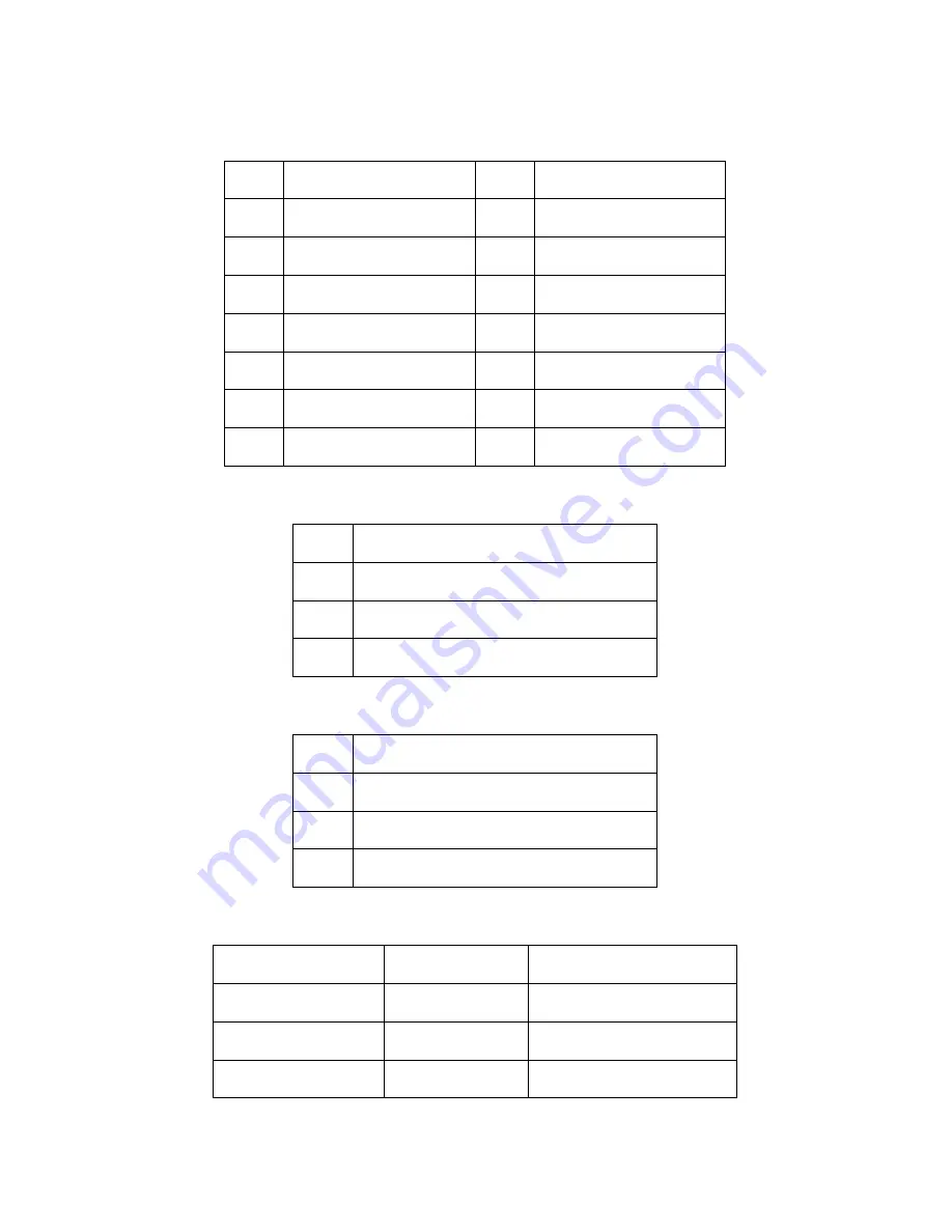
3.7.2 Fan Board Connector Pin Definition
J3 and PWM Pin Header
FAN1~FAN6 Fan Connector Pin Out
J1, J2 Big 4-pin Power Connector Pin Out
Each system fan connects to the fan board as listed below:
1
FAN1 PWM
2
GND
3
FAN2 PWM
4
GND
5
FAN3 PWM
6
GND
7
FAN4 PWM
8
GND
9
FAN5 PWM
10
GND
11
FAN5 PWM
12
GND
13
FAN PWM INPUT
14
KEY PIN
15
MUTE+
16
GND
1
GND
2
VDD +12V
3
CLOCK
4
PWM
1
VDD +12V
2
GND
3
GND
4
VDD +5V
System Fan
Connects to
Fan Board
System Fan1
Æ
Fan1 connector
System Fan2
Æ
Fan3 connector
System Fan3
Æ
Fan5 connector
Содержание Tank FT48 B5382
Страница 1: ...Tank FT48 B5382 Service Engineer s Manual...
Страница 2: ......
Страница 22: ...14 Chapter 1 Overview 1 5 7 Motherboard Layout...
Страница 24: ...16 Chapter 1 Overview 1 5 9 B5382 System Block Diagram...
Страница 26: ...18 Chapter 1 Overview...
Страница 94: ...86...


