background image


http://www.tyan.com 

60 

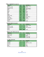
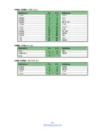
J29: 2*10 Pin FAN I/O Connector 

Definition 

Pin 

Pin 

Definition 

FAN_TACH1 

FAN_TACH6 

FAN_TACH2 

FAN_TACH7 

FAN_TACH3 

FAN_TACH8 

FAN_TACH4 

FAN_TACH9 

FAN_TACH5 

10 

FAN_TACH10 

GND 

11 

12 

KEY 

CON_PWM2 

13 

14 

CON_PWM1 

FAN_TACH11 

15 

16 

BMC_3V3_DAT 

FAN_TACH12 

17 

18 

BMC_3V3_CLK 

VCC3_AUX 

19 

20 

CON_PWM3 


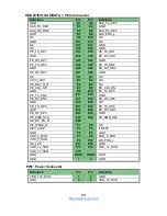
SATA0_3/SATA4_7: Mini SAS Connector 

Definition 

Pin 

Pin 

Definition 

GND 

A1 

A2 

SAS_TX_DP0 

SAS_TX_DN0 

A3 

A4 

GND 

SAS_TX_DP1 

A5 

A6 

SAS_TX_DN1 

GND 

A7 

A8 

SAS_SIO_CLK_A 

SAS_SIO_END_A 

A9 

A10 

GND 

SMB2_CLK3 

A11 

A12 

GND 

SAS_TX_DP2 

A13 

A14 

SAS_TX_DN2 

GND 

A15 

A16 

SAS_TX_DP3 

SAS_TX_DN3 

A17 

A18 

GND 

GND 

B1 

B2 

SAS_RX_DP0 

SAS_RX_DN0 

B3 

B4 

GND 

SAS_RX_DP1 

B5 

B6 

SAS_RX_DN1 

GND 

B7 

B8 

SMB2_DATA3 

GND 

B9 

B10 

SAS_SIO_DOUT_A 

SAS_SIO_DIN_A 

B11 

B12 

GND 

SAS_RX_DP2 

B13 

B14 

SAS_RX_DN2 

GND 

B15 

B16 

SAS_RX_DP3 

SAS_RX_DN3 

B17 

B18 

GND 

GND 

G1 

G2 

GND 

GND 

G3 

G4 

GND 

GND 

G5 

G6 

GND 

GND 

G7 

G8 

GND 


Содержание GT62F-B8026

Страница 1: ...GT62F B8026 Service Engineer s Manual...

Страница 2: ...ity or warranties relating to fitness for a particular purpose or merchantability TYAN retains the right to make changes to produce descriptions and or specifications at any time without notice In no...

Страница 3: ...limits are designed to provide reasonable protection against harmful interference when the equipment is operated in a commercial environment This equipment generates uses and can radiate radio freque...

Страница 4: ...ncture mutilate or dispose of battery in fire There will be danger of explosion if battery is incorrectly replaced Replace only with the same or equivalent type recommended by manufacturer Dispose of...

Страница 5: ...list and accessories describes the external components gives a table of key Chapter2 Setting Up This chapter Covers procedures on installing the CPU memory modules add on card and hard drives Give an...

Страница 6: ...e of this pin If your outlet does not support this kind of plug contact your electrician to replace your obsolete outlet Do not place anything on the power cord Place the power cord where it will not...

Страница 7: ...ns are not observed Consult equipment documentation for specific details Caution Slide mounted equipment is not to be used as a shelf or a work space Warning This symbol indicates the presence of haza...

Страница 8: ...or damage to the equipment Observe local occupational health and safety requirements and guidelines for manual materials handling Do not attempt to move a rack by yourself a minimum of two people are...

Страница 9: ...power to the rack is not overloaded This will reduce the risk of personal injury fire or damage to the equipment The total rack load should not exceed 80 percent of the branch circuit rating Consult...

Страница 10: ...y to temperatures higher than 60 C 140 F The system battery is not replaceable If the battery is replaced by an incorrect type there is danger of explosion Replace the battery only with a spare design...

Страница 11: ...gloves when you remove or replace system components they can become hot to the touch If the product sustains damage requiring service disconnect the product from the AC electrical outlet and refer se...

Страница 12: ...e Memory 35 2 1 5 Installing Hard Drives 37 2 1 6 Installing the Add On Card 39 2 2 Rack Mounting 42 2 2 1 Installing the Server in a Rack 43 2 2 2 Installing the inner Rails to the Chassis 43 2 2 3 I...

Страница 13: ...e Motherboard 74 Chapter 4 BIOS Setup 76 4 1 About the BIOS 76 4 2 Main Menu 78 4 3 Advanced Menu 80 4 4 Chipset Menu 111 4 5 AMD CBS Menu 116 4 6 Server Management 131 4 7 Security 136 4 8 Boot 141 4...

Страница 14: ...system is capable of offering scalable 32 and 64 bit computing high bandwidth memory design and lightning fast PCI E bus implementation GT62F B8026 not only empowers your company in today s demanding...

Страница 15: ...2 USB 3 0 port External Drive Bay Type Q ty 2 5 Hot swap NVMe 10 HDD backplane support NVMe SATA 6 0Gb s Supported HDD Interface 2 SATA 6Gb s 8 NVMe 10 2 5 NVMe System Cooling Configuration FAN 4 4cm...

Страница 16: ...PHY Realtek RTL8211E Storage SATA Connector 2 SATA DOM Controller Direct from AMD CPU Speed 6 0 Gb s RAID N A M 2 connector 2 M 2 connectors 22110 2280 2260 2242 by PCI E SATA interface NVMe 8 PCI E...

Страница 17: ...te platform flash USB 2 0 virtual hub AST2500 IPMI Feature 24 bit high quality video compression 10 100 1000 Mb s MAC interface BIOS Brand ROM size AMI 32MB Feature Hardware Monitor Boot from USB devi...

Страница 18: ...stem Form Factor 1U Rackmount Chassis Model GT62F Dimension D x W x H 24 6 x 17 2 x 1 72 625 4 x 436 x 43 6mm Motherboard S8026GM2NR LE Gross Weight 20 kg 44 lbs Net weight 10 5kg 23 5 lbs Front Panel...

Страница 19: ...MM slots DIMM Type Speed DDR4 ECC RDIMM LRDIMM 2666 2400 Capacity Up to 1 024GB RDIMM LRDIMM Memory channel 8 Channels Memory voltage 1 2V Expansion Slots PCI E 2 PCI E Gen3 x16 slots Pre install TYAN...

Страница 20: ...memory system environment Voltage Monitors voltage for CPU memory chipset power supply LED Over temperature warning indicator Fan PSU fail LED indicator Others Watchdog timer support Server Management...

Страница 21: ...ulation FCC DoC Class A CE DoC Class A VCCI Class A CB LVD Yes RCM Class A Operating Environment Operating Temp 10 C 35 C 50 F 95 F Non operating Temp 40 C 70 C 40 F 158 F In Non operating Humidity 90...

Страница 22: ...1286G62F BP12E 10 B8026 HDD Backplane pre installed 1 M1716G75 Front Panel Board pre installed 1 M1620G62F D PDB or Tiger PDB pre installed 1 M7106 L16 1F Riser Board pre installed 1 M7106 R16 1F Rise...

Страница 23: ...s website for service http www tyan com GT62F B8026 Accessory Kit 1 Sliding rail 1 CPU Heatsink 2 US Power Cord 2 EU Power Cord 1 Mounting Ear Kit x1 1 Air Duct 1 MEZZ card screw package 2 2 5 HDD sc...

Страница 24: ...e product 1 3 1 System Front View HDD Sequence B8026G62FV10HR NVMe1 NVMe3 NVMe5 NVMe7 NVMe9 NVMe0 NVMe2 NVMe4 NVMe6 NVMe8 HDD Sequence B8026G62FV10HR LE HDD1 SSD1 HDD3 SSD3 HDD5 SSD5 HDD7 SSD7 HDD9 SS...

Страница 25: ...reen off Blue Solid On Warning System normal Off System Normal Amber Off System Warning Amber Solid On System alert Amber HDD HDD Ready Off HDD Access Green Blinking HDD Ready Green Off HDD Access Bli...

Страница 26: ...GA Port 9 1Gb RJ45 LAN3 from PHY dedicated for BMC IPMI 1 3 3 LED Definitions 1Gbps LAN Port LAN Indication 10 100 1000 Mbps LAN Link Activity LED Scheme Left LED Link Activity Right LED Speed No Link...

Страница 27: ...AS SATA NVMe hot swap SSDs HDDs 3 M1286G62F BP12E 10 B8026 HDD Backplane 4 4 cabled fans 5 CPU socket Heatsink 6 Memory Slots 7 PCIE3 0 SLOT x24 PESLOT2 8 PCIE3 0 SLOT x24 PESLOT1 9 OCP A Slot OCP1_A...

Страница 28: ...revent you from accidentally damaging the internal components 2 0 3 Tools The following procedures require only a few tools including the following A cross head Phillips screwdriver A grounding strap...

Страница 29: ...sis of the unit case or the bare metal body of any other grounded appliance Avoid touching motherboard components IC chips connectors memory modules and leads The motherboard is pre installed in the s...

Страница 30: ...Removing the Chassis Cover Follow these instructions to remove GT62F B8026 chassis cover 1 Remove the side screw on the chassis cover as in the small diagram 2 Loosen the Thumb screw on the back side...

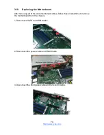
Страница 31: ...2 1 2 Removing the Air Duct 1 Remove the air duct from the chassis...

Страница 32: ...river to loosen the screws securing the force frame in a sequential order 3 2 1 Note The force frame will automatically eject after the captive screws are being released 2 By placing your both index f...

Страница 33: ...ion observe the following NOTE During installation observe the following 1 Make sure to push the carrier frame with package towards the end of the rail frame until it clicks into place 2 Do not drop t...

Страница 34: ...e with the installed package Then push both edges of the rail frame firmly until it locks in place 7 Close the force frame Then use a T20 Torx screwdriver to tighten the screws to secure the force fra...

Страница 35: ...o the motherboard 1 Press the memory slot locking levers in the direction of the arrows as shown in the following illustration 2 Align the memory module with the slot When inserted properly the memory...

Страница 36: ...DIMM Location...

Страница 37: ...eGT62F B8026 supports 10 2 5 Hard Drives Follow these instructions to install a hard drive 2 5 Hard Disk Drive 1 Located at the 2 5 HDD tray 2 Press the locking lever to release the 2 5 SSD HDD tray 3...

Страница 38: ...he 4 screws to detach HDD tray bracket 5 Place a hard drive into the drive tray Use four screws to secure the HDD 6 Reinsert the HDD tray into the chassis 7 Press the locking lever to lock the 2 5 SSD...

Страница 39: ...ansion slot which is available with riser card The following instructions are for Add On card installation You may refer to the procedures below for the installation 1 Remove the screw of PCI E bracke...

Страница 40: ...4 Insert the PCI E card in the direction of arrows as shown...

Страница 41: ...5 Screw the PCI E cards firmly to the riser card bracket...

Страница 42: ...he necessary components the TYAN GT62F B8026 can be mounted in a rack using the supplied rack mounting kit Rack mounting kit Sliding Rails x 2 Mounting Ears including screws x 2 Screws Kit x 1 Mountin...

Страница 43: ...ts have been installed and that the unit has been fully tested However to make the installation easier we suggest that you remove all HDD trays before you insert the chassis into the rack 2 2 2 Instal...

Страница 44: ...inner sliding rail forward to secure it to the chassis And secure the inner rail to the chassis with 2 screws 5 Screw the mounting ear to each side of TYAN GT62F as shown using two screws of 6 32 L5 3...

Страница 45: ...re the outer rail to the rack using 8 M5 washer A screws for each side 2 2 4 Rack mounting the Server 1 Lift the unit and then insert the inner slide rails into the middle rails 2 Press the white butt...

Страница 46: ...http www tyan com 46 3 Secure the mounting ears of chassis to the rack with 2 M5 15L C screws...

Страница 47: ...d components including the S8026GM2NRE S8026GM2NR LE Motherboard M1716G75 FPB Front Panel Board M1274G62B BP12 10 B8026 M1286G62F BP12E 10 B8026 Backplane M7106 L16 1F M7106 R16 1F Riser Card System F...

Страница 48: ...Follow Chapter 2 1 1 to remove the cover of GT62F B8026 3 4 Replacing the Riser Card 1 The GT62F B8026 has preinstalled 2 riser cards Release the 2 screw to lift the riser bracket from the chassis Rem...

Страница 49: ...http www tyan com 49 3 Remove the 2 screws to release the M7106 R16 1F riser card 4 Remove the 2 screws to release the M7106 L16 1F riser card...

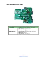
Страница 50: ...http www tyan com 50 3 4 1 Riser Card Features M7106 L16 1F Riser Card M7106 R16 1F Riser Card...

Страница 51: ...r system fans Disconnect the fan cable which you need to replace up 2 Take out the fan module from the chassis 3 Release the rubber screws and the push pins from the fan 4 Replace the failed fan modul...

Страница 52: ...ow these instructions to replace the M1274G62B BP12E 10 B8026 M1286G62 BP12E 10 B8026 HDD Backplane 1 First pull the HDD trays slightly forwards to make the HDD BP Board easier to uninstall 5 Disconne...

Страница 53: ...http www tyan com 53 7 Remove the eight screws securing the bracket to the HDD backplane...

Страница 54: ...SAS SATA HDD Connectors 4 MINI SAS HD Connector connect to MB 2 MINI SAS Connector connect to MB 2 SATA connector connect to MB 1 2 10 Pin FAN connector connect to MB 6 8 Pin FAN connector connect to...

Страница 55: ...tor NVMe Connector NVMe Connector NVMe Connector SAS SATA PCIe HDD Connector SAS SATA PCIe HDD Connector SAS SATA PCIe HDD Connector SAS SATA PCIe HDD Connector SAS SATA HDD Connector SAS SATA HDD Con...

Страница 56: ...View Rear View PCB Dimensions 420 4 36 7 2mm Thickness 2mm Layer 8 layers Integrated I O 10 HDD NVMe Connector 5 OCCulink Connector 6 FAN Connector 1 4X2pin Power Connector 1 4Pin Power Connector 2 S...

Страница 57: ...Culink Connector OCCulink Connector OCCulink Connector OCCulink Connector HDD NVMe Connector HDD NVMe Connector HDD NVMe Connector HDD NVMe Connector HDD NVMe Connector HDD NVMe Connector HDD NVMe Con...

Страница 58: ...8 GND NC E1 E2 NC VCC3_AUX E3 E4 NC PE_RST_N_R E5 E6 NC PE_CLK_DP E7 E8 PE_CLK_DN GND E9 E10 PE_TX_DP0 PE_TX_DN0 E11 E12 GND PE_RX_DN0 E13 E14 PE_RX_DP0 GND E15 E16 NC PE_TX_DP3 E17 E18 PE_TX_DN3 GND...

Страница 59: ...10 HD2_PRS_L HD2_LED P11 P12 GND HD2_VDD12 P13 P14 VDD12 VDD12 P15 GND GND1 GND2 GND SATA8 9 SATA Connector Definition Pin Pin Definition GND 1 2 SAS_TX_DP8 SAS_TX_DN8 3 4 GND SAS_RX_DN8 5 6 SAS_RX_DP...

Страница 60: ...Mini SAS Connector Definition Pin Pin Definition GND A1 A2 SAS_TX_DP0 SAS_TX_DN0 A3 A4 GND SAS_TX_DP1 A5 A6 SAS_TX_DN1 GND A7 A8 SAS_SIO_CLK_A SAS_SIO_END_A A9 A10 GND SMB2_CLK3 A11 A12 GND SAS_TX_DP2...

Страница 61: ...SCLOCK P3V3_AUX 9 10 HD_ERROR_LED PW2 Power Connector Definition Pin Pin Definition VDD_12V_RUN 1 2 GND GND 3 4 VDD_5V_RUN J7 Front Panel Connector Signal Pin Pin Signal TACH1 1 2 TACH6 TACH2 3 4 TACH...

Страница 62: ...14 B14 PEBp2 PEAp2 A15 B15 PEBp2 GND5 A16 B16 GND17 PEAn3 A17 B17 PEBp3 PEAn3 A18 B18 PEBp3 GND6 A19 B19 GND18 A20 A20 B20 B20 A21 A21 B21 B21 GND7 A22 B22 GND19 PEAn4 A23 B23 PEBp4 PEAn4 A24 B24 PEBp...

Страница 63: ...Solid OFF Identify Locate the HDD Blinking 1Hz OFF Rebuild Blinking 4Hz OFF B8026G62FE10HR HDD Status ODn0 Act ODn1 Locate ODn2 Fail Activity LED Color Green Status LED Color Amber Drive not Present x...

Страница 64: ...he Front Panel Board Follow these instructions to replace the M1716G75 FPB Front Panel Board 1 Unscrew the front panel tray 2 Pull the front panel tray forwards 4 Disconnect the control cable and USB3...

Страница 65: ...http www tyan com 65 5 Unscrew the front panel board from the front panel tray for a new one 6 Reinstall the Front Panel Board into the chassis following the steps in reverse...

Страница 66: ...Panel Board Features Front View Rear View Form Factor 28 x 35 4 x 1 6 mm 4 layer PCB Specifications I O 2 USB3 0 Port LED Indicators 1 HDD LED 1 Warning LED 2 LAN LED 1 Power ID LED Switch 1 Reset Bu...

Страница 67: ...ation Definition HDD_LED HDD LED BMC_EVENT_LED Warning LED LAN1_LED LAN1 LED LAN2_LED LAN2 LED ID_PW_LED Power ID LED J1 USB3 0 Port J2 USB3 0 Port J3 Reset Button J5 ID Button J6 Power Button J4 USB3...

Страница 68: ...er Supply To replace the power supply follow these instructions 1 Located at the power supply usage 2 Free the power from the power socket 3 Replace a new power supply and reinsert it into the power s...

Страница 69: ...ore you follow these instructions to replace the M1620G62F D PDB Power Distribution Board 1 Disconnect all the power cables 2 Unscrew to take off the power distribution board and replace with a new on...

Страница 70: ...1620G62F D PDB 3 9 2 Connector Definitions M1620 Location Definition J2 J3 PWR1 PW2 PW5 PW3 PW4 PW1 DOM_5V_PW1 DOM_5V_PW2 Power Supply slot Power Supply slot ATX Power 12x2 ATX Power 4x2 ATX Power 4x2...

Страница 71: ...PDB Redundant Control Board Form Factor 114 62mm L x 105 6mm W x 28mm H Specifications CON1 CON2 Input connector CON3 Mini fit 24 pin power connector CON4 CON5 HDD 4 pin power connector CON6 PMBus 5 p...

Страница 72: ...N DC_GOOD S9 S10 A1 SMBus address 5Vsb S11 S12 5Vsb C_R S13 S14 SGND PRESENT A0 SMBus address S15 S16 B P SIG N A S17 S18 N A N A S19 S20 SGND B P FAIL S21 S22 N A 5Vsb S23 S24 5Vsb CON3 Mini fit 24 p...

Страница 73: ...8 PWR OK 5Vsb 9 10 12V 12V 11 12 3 3V 3 3V 13 14 12V SGND 15 16 PS ON SGND 17 18 SGND SGND 19 20 N A 5V 21 22 5V 5V 23 24 SGND CON6 PMBus 5 pin Definition Pin Pin Definition SCL 1 2 SDA SMBAlert 3 4 S...

Страница 74: ...After removing all of the aforementioned cables follow these instructions to remove the motherboard from the chassis 1 Disconnect SATA and USB cables 2 Disconnect the power cable and PSMI Cable 3 Dis...

Страница 75: ...erboard After removing all of the aforementioned cables follow the instructions below to remove the motherboard from the chassis 1 Remove the nine screws securing the motherboard to the chassis 2 Care...

Страница 76: ...to change and therefore may not match exactly what is displayed on screen This section describes the BIOS setup program The setup program lets you modify basic configuration settings The settings are...

Страница 77: ...eemingly small change to the Chipset setup options may cause the system to become unstable or unusable 4 1 4 Setup Variations Not all systems have the same BIOS setup layout or options While the basic...

Страница 78: ...that can directly be changed within the Main Setup screen BIOS Information It displays BIOS related information Product Name It displays Product information BIOS Version It displays BIOS version info...

Страница 79: ...Date Set the Date Use Tab to switch between Date elements Default Ranges Year 2005 2099 Months 1 12 Days dependent on month System Time Adjust the system clock HH 24 hours format MM Minutes SS Second...

Страница 80: ...Configuration CPU Configuration parameters Onboard Device Configuration Onboard Device and Function Configuration PCIE Slot Configuraion Onboard PCIE Slot Configuration Trusted Computing Trusted Comp...

Страница 81: ...on SIO Configuration PCI Subsystem Settings PCI PCI X and PCI Express Settings CSM Configuration CSM Configuration Enable Disable Option ROM execution setting etc NVMe Configuration NVMe Device Option...

Страница 82: ...tyan com 82 4 3 1 CPU Configuration SVM Mode Enable disable CPU virtulization Disabled Enabled SMEE Control secure memory encryption enable Disabled Enabled CPU 0 Information View Information related...

Страница 83: ...http www tyan com 83 4 3 1 1 CPU0 Information...

Страница 84: ...d Active Video Select between onboard or external VGA support Onboard Offboard Onboard LAN B5720 Enable Disable Onboard LAN Device Disabled Enabled LAN1 Port1 OPROM Enable Disable Load Option ROM For...

Страница 85: ...MI Button Enable or disable NMI button Disabled Enabled Clock Spread Spectrum Enable Disable CG1_PLL Spread Spectrum Disabled Enabled Serial IRQ Mode Configure Serial IRQ Mode Quiet Continuous 4 3 3 P...

Страница 86: ...th Configuration Auto is detected by GPIO x8x8 x16 x4x4x4x4 x8x8 x16 Auto Riser L Down Slot Link Width Configution Setting Pcie Slot Link Width x4x4 x8 Riser R Middle Slot Link Width Configuration Rig...

Страница 87: ...k Speed Configuration Auto Gen1 2 5 GT s Gen2 5 GT s Gen3 8 GT s Riser L Middle Slot Link Speed Onboard PCIE Slot Link Speed Configuration Auto Gen1 2 5 GT s Gen2 5 GT s Gen3 8 GT s Riser L Down Slot...

Страница 88: ...ed Computing Security Device Support Enable or disable BIOS support for security device O S will not show Security device O S will not show Security Device TCG EFI protocol and INT1A interface will no...

Страница 89: ...www tyan com 89 4 3 5 Hardware Health Configuration Auto Fan Control Auto Fan Control help Disabled Enabled BMC Alert Beep Enable Disable BMC Alert Beep On Off PMBus support PMBus Support Disabled Ena...

Страница 90: ...90 4 3 5 1 Sensor Data Register Monitoring When you enter the Sensor Data Register Monitoring submenu you will see the following dialog window pop out Please wait 8 10 seconds NOTE 1 SDR can not be m...

Страница 91: ...http www tyan com 91...

Страница 92: ...tings Wake system from S5 Enable or disable system wake on alarm event Select Fixed time system will wake on the hr min sec specified Select dynamic time system will wake on the current time increase...

Страница 93: ...ial Port for Out Of Band Management Windows Emergency Services EMS Console Redirection Console redirection enable or disable Disabled Enabled Console Redirection Settings The settings specify how the...

Страница 94: ...rial port transmission speed The speed must be matched on the other side Long or noisy lines may require lower speeds 38400 9600 19200 115200 57600 Data Bits 8 7 Parity A parity bit can be sent with t...

Страница 95: ...to stop the data flow Once the buffers are empty a start signal can be sent to re start the flow Hardware flow control uses two wires to send start stop signal None Hardware RTS CTS VT UTF8 Combo Key...

Страница 96: ...VT100 Extends VT100 to support color function keys etc VT UTF8 Uses UTF8 encoding to map Unicode chars onto 1 or more bytes VT UTF8 VT100 VT100 ANSI Bits per Second Select serial port transmission sp...

Страница 97: ...re more than 1 stop bit 1 2 Flow Control Flow Control can prevent data loss from buffer overflow When sending data if the receiving buffers are full a stop signal can be sent to stop the data flow Onc...

Страница 98: ...esolution On Legacy OS the Number of Rows and Columns supported redirection 80x24 80x25 Redirect After POST when Bootloader is selected then Legacy Console Redirection is disabled before booting to le...

Страница 99: ...r OS through a serial port COM1 COM2 Terminal Type VT UTF8 is the preferred terminal type for out of band management The next best choice is VT100 and then VT100 See above in Console Redirection Setti...

Страница 100: ...en sending data if the receiving buffers are full a stop signal can be sent to stop the data flow Once the buffers are empty a start signal can be sent to restart the flow Hardware flow control uses t...

Страница 101: ...e Serial Port 1 View and Set Basis properties of the SIO Logical device Like IO Base IRQ Range DMA Channel and Device Mode Active Serial Port 2 View and Set Basis properties of the SIO Logical device...

Страница 102: ...abled Possible Allows the user to change the device resource settings New settings will be reflected on this setup page after system restarts Use Automatic Settings IO 3F8h IRQ 4 DMA IO 3F8h IRQ 3 4 5...

Страница 103: ...abled Possible Allows the user to change the device resource settings New settings will be reflected on this setup page after system restarts Use Automatic Settings IO 3F8h IRQ 4 DMA IO 3F8h IRQ 3 4 5...

Страница 104: ...vices to be decoded in Above 4G Address Space Only if System supports 64 bit PCI Decoding Enabled Disabled SR IOV Support If system has SR IOV capable PCIe devices this option Enable or Disable Single...

Страница 105: ...http www tyan com 105 4 3 9 1 PCI Express Subsystem Maximum Payload Set Maximum Payload of PCI Express Device or allow System BIOS to select the value Auto 128 Bytes 256 Bytes 512 Bytes...

Страница 106: ...etwork Controls the execution of UEFI and legacy PXE OpROM Do not launch UEFI legacy Storage Controls the execution of UEFI and legacy PXE OpROM Do not launch UEFI legacy Video Controls the execution...

Страница 107: ...http www tyan com 107 4 3 11 NVMe Configuration...

Страница 108: ...http www tyan com 108 4 3 12 SATA Configuration...

Страница 109: ...abled Disabled Auto XHCI Hand off This is a workaround for OSes without XHCI hand off support The XHCI ownership change should be claimed by XHCI driver Enabled Disabled USB Mass Storage Driver Suppor...

Страница 110: ...vice reset time out USB mass storage device Start Unit command time out 20 sec 10 sec 30 sec 40 sec Device power up delay Maximum time the device will take before it properly reports itself to the Hos...

Страница 111: ...tyan com 111 4 4 Chipset Menu SMT Mode simultaneous multithreading OFF 1T single thread Auto 2T two thread if capable off Auto North Bridge North Bridge Parameters Error Management Error Management s...

Страница 112: ...http www tyan com 112 4 4 1 North Bridge Configuration Memory Configuration Memory Configuration Socket 0 Configuration View Information related to Socket 0...

Страница 113: ...http www tyan com 113 4 4 1 1 Memory Configuration Memory Clock This option Allows User to select different memory Clock Default value is 2400 MT s Auto 1333MHz 1600MHz 1866MHz 2133MHz 2400MHz 2667MHz...

Страница 114: ...http www tyan com 114 4 4 1 2 Socket 0 Information...

Страница 115: ...ble PFEH cloak individual banks and mask deferred error interrupts from each bank Disabled Enabled NOTE The item Platform First Error Handling must be set up to Enabled the following item will appear...

Страница 116: ...http www tyan com 116 4 5 AMD CBS Menu...

Страница 117: ...Submenu Core Performance Boost Allows Core Performance Boost CPB to be forced to disabled Disabled Auto Global C state Control Controls IO based C state generation and DF C states Disabled Enabled Aut...

Страница 118: ...http www tyan com 118 4 5 1 1 Core Thread Enablement Submenu...

Страница 119: ...ubmenu Downcore control Sets the number of cores to be used Once this option has been used to remove any cores a POWER CYCLE is required in order for future selections to take effect TWD 1 1 TWD 2 0 T...

Страница 120: ...terleaving Controls fabric level memory interleaving AUTO none channel die socket Note that channel die and socket has requirements on memory populations and it will be ignored if the memory doesn t s...

Страница 121: ...http www tyan com 121 4 5 3 UMC Common Options Submenu...

Страница 122: ...http www tyan com 122 4 5 3 1 DDR4 Common Options Submenu...

Страница 123: ...www tyan com 123 4 5 3 1 1 Common RAS Options Submenu Data Poisoning Enable disable data poisoning UMC_CH EccCtrl UcFatalEn UMC_CH EccCtrl WrEccEn Should be enabled disabled together Disabled Enabled...

Страница 124: ...1 1 1 ECC Configuration Submenu DRAM ECC Symbol Size DRAM ECC Symbol Size x4 x8 UMC_CH EccCtrl EccSymbolSize X4 x8 Auto DRAM ECC Enable Use this option to enable disable DRAM ECC Auto will set ECC to...

Страница 125: ...http www tyan com 125 4 5 3 2 Security Submenu Data Scramble Data scrambling DataScrambleEn Enabled Disabled Auto...

Страница 126: ...Submenu Chipselect Interleaving Interleave memory blocks across the DRAM chip selects for node 0 Disabled Auto BankGroupSwap This is an advanced performance setting specifies if the system should use...

Страница 127: ...terminism settings power performance Auto Power Perfomance cTDP Control Auto Use the fused cTDP Manual User can set customized cTDP Manual Auto ACS Enable Supported functions of Access Control Service...

Страница 128: ...http www tyan com 128 4 5 4 1 NB Configuration Submenu IOMMU Enable Disable IOMMU Disabled Enabled Auto...

Страница 129: ...http www tyan com 129 4 5 4 FCH Common Options Submenu...

Страница 130: ...http www tyan com 130 4 5 4 1 Ac Power Loss Options Submenu Restore Ac Power Loss Select Ac Loss Control Method Power Off Power On Last State...

Страница 131: ...mer Expiration value 3 minutes 4 minutes 5 minutes 6 minutes FBR 2 Timer Policy Configure how the system should respond if the FRB 2 Timer expires Not available if FRB 2 Timer is disabled Do Nothing R...

Страница 132: ...sabled 5 minutes 10 minutes 15 minutes 20 minutes OS Wtd Timer Policy Configure how the system should respond if the OS Boot Watchdog Timer expires Not available if OS Boot Watchdog Timer is disabled...

Страница 133: ...boot Enabled Disabled Erase SEL Choose options for erasing SEL No Yes on next reset No on every reset When SEL is Full Choose options for reactions to a full SEL Do Nothing Erase Immediately Log EFI...

Страница 134: ...http www tyan com 134 4 6 2 BMC Network Configuration Submenu...

Страница 135: ...y BMC network parameters during BIOS phase Unspecified Static DynamicBmcDhcp DynamicBmcNonDhcp Configure IPV4 support Management Port 2 Enable Disable BMC Share NIC Disabled Enabled Configure IPV6 sup...

Страница 136: ...trator Password Set Administrator Password User Password Set User Password Security Frozen Mode Enable or disable HDD security freeze lock Disable to support secure erase function Disabled Enabled Sec...

Страница 137: ...rolled System mode is User Deployed and CSM function is disabled Enabled Disabled Secure Boot Mode Secure Boot mode selector Custom mode enables users to change Image execution policy and manage secur...

Страница 138: ...o User Mode install all Factory Default keys Enroll Efi Image Allow the image to run in Secure Boot mode Enroll SHA256 hash of the binary into Autorized Signature Database db Platform Key PK Enroll Fa...

Страница 139: ...ertificate in a EFI_SIGNATURE_LIST b EFI_CERT_X509 DER encoded c EFI_CERT_RSA2048 bin d EFI_CERT_SHA256 384 512 2 Authenticated UEFI Variable 3 EFI PE COFF Image SHA256 Key Source Default External Mix...

Страница 140: ...t External Mixed Test OsRecovery Signatures Enroll Factory Defaults or load certificates from a file 1 Public Key Certificate in a EFI_SIGNATURE_LIST b EFI_CERT_X509 DER encoded c EFI_CERT_RSA2048 bin...

Страница 141: ...0xFFFF means indefinite waiting Bootup NumLock State Select the keyboard NumLock state Off On Quiet Boot Enable or disable Quiet Boot option Disabled Enabled Endless Boot Enabled or Disabled Endless...

Страница 142: ...http www tyan com 142 Boot Option Priorities Boot Option 1 Sets the system boot order Device Name Disabled Delete Boot Option Remove an EFI boot option from the boot order...

Страница 143: ...http www tyan com 143 4 8 1 Delete Boot Option Configuration Delete Boot Option Sets the system boot order Device Name Select one to Delete...

Страница 144: ...it Exit system setup without saving any changes Save Changes and Reset Reset the system after saving the changes Discard Changes and Reset Reset system setup without saving any changes Save Changes Sa...

Страница 145: ...Defaults Restore Load Default values for all the setup options Save as User Defaults Save the changes done so far as User Defaults Restore User Defaults Restore the User Defaults to all the setup opti...

Страница 146: ...e motherboard A table of BIOS Temp sensor name explanation is also included for readers reference NOTE The red dot indicates the sensor Fan and Temp Sensor Location 1 Fan Sensor It is located in the t...

Страница 147: ...http www tyan com 147 NOTE The system temperature is measured in a scale defined by AMD not in Fahrenheit or Celsius BIOS Temp Sensor Name Explanation...

Страница 148: ...hest temperature of CPU0 D1UMC0 channel A slot P0_D1_UMC1_CH_B The highest temperature of CPU0 D1 UMC1 channel B slot P0_D0_UMC1_CH_C The highest temperature of CPU0 D0 UMC1 channel C slot P0_D0_UMC0_...

Страница 149: ..._4 Fan speed of SYS_FAN_4 SYS_FAN_5 Fan speed of SYS_FAN_5 SYS_FAN_6 Fan speed of SYS_FAN_6 SYS_FAN_7 Fan speed of SYS_FAN_7 SYS_FAN_8 Fan speed of SYS_FAN_8 SYS_FAN_9 Fan speed of SYS_FAN_9 SYS_FAN_1...

Страница 150: ...o install the IO Plate for OCP Card Here shows how to install the IO Plate for the dual port LAN card M7106 X557 2T2E 1 Unscrew the riser card bracket 2 Remove the riser card bracket from the chassis...

Страница 151: ...ut the IO plate for LAN card Use a screwdriver to break the LAN port s semi shearing Break one semi shearing if a single port LAN card is installed Break both for a dual port LAN card 5 Insert the IO...

Страница 152: ...http www tyan com 152 7 Insert the LAN card into the OCP slot...

Страница 153: ...http www tyan com 153 8 Secure the LAN card to the chassis...

Страница 154: ...n4 FAN5 2 FP Control Cable and USB Cable M1716G75 FPB Control Board to S8026 MB M1716G75 FPB Connect to S8026 FP Ctrl Cable J4 FPIO_1 USB Cable J7 USB3_FPIO1 3 OCulink Cable SATA Cable FAN Ctrl Cable...

Страница 155: ...7 Fan Ctrl Cable J29 FAN_HD1 4 Power Cables TD15 0128 02 PDB to S8026 MB TD15 0128 02 Connect to S8026 2x12P Cable CON3 PW1 2x4P Cable CON7 PW3 PSMI Cable CON6 PSMI1 TD15 0128 02 PDB to M1274 Backplan...

Страница 156: ...06 L16 1F 5411T5650006 M7106 L16 1F Riser Card M7106 R16 1F 5411T5650007 M7106 R16 1F Riser Card Rack Mounting Parts FRU AS 0020 452T15200002 Slide Rail Kit Cable FRU CS 0680 422T57100003 Oculink to M...

Страница 157: ...http www tyan com 157 NOTE...

Страница 158: ...expectations TYAN s website http www tyan com provides easy to access resources such as in depth Linux Online Support sections with downloadable Linux drivers and comprehensive compatibility reports...

Страница 159: ...oper maintenance of products NOTE A receipt or copy of your invoice marked with the date of purchase is required before any warranty service can be rendered You may obtain service by calling the manuf...

Отзывы: