TYAN FT48A-B7070 Скачать руководство пользователя страница 46


http://www.tyan.com 


46 

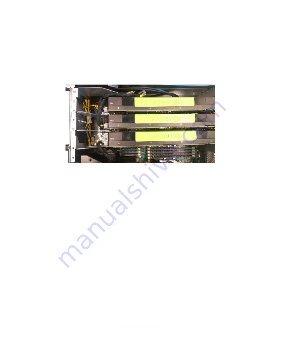
The FT48A-B7070 supports

 NVIDIA

®


K40/K80


GPU


cards.   

Follow these instructions was the example to install K80 GPU cards. 
 

Caution!


The GPU power cable must avoid to be routed through the air inlet, because air 
inlet block will lead to GPU module overheated. This image illustrates the right 
power cable routing. 


Содержание FT48A-B7070

Страница 1: ...FT48A B7070 Service Engineer s Manual...

Страница 2: ...TYAN products including liability or warranties relating to fitness for a particular purpose or merchantability TYAN retains the right to make changes to produce descriptions and or specifications at...

Страница 3: ...es and can radiate radio frequency energy and if not installed and used in accordance with the instruction manual may cause harmful interference to radio communications Operation of this equipment in...

Страница 4: ...on to the FT48A B7070 barebones standard parts list external components list the key components of motherboard and provicd block diagram of the system Chapter 2 A complete introduction of the procedur...

Страница 5: ...the purpose of this pin If your outlet does not support this kind of plug contact your electrician to replace your obsolete outlet Do not place anything on the power cord Place the power cord where it...

Страница 6: ...r with the safety information in this guide before you install operate or service TYAN products Symbols on Equipment Caution This symbol indicates a potential hazard The potential for injury exists if...

Страница 7: ...t Chassis Do not block or cover the openings to the system Never push objects of any kind through openings in the equipment Dangerous voltages might be present Conductive foreign objects can produce a...

Страница 8: ...epth must allow for proper serviceability and cable management Ensure that there is adequate airflow in the rack Improper installation or restricted airflow can damage the equipment The rack cannot ha...

Страница 9: ...ment Batteries The system battery contains lithium manganese dioxide If the battery pack is not handled properly there is risk of fire and burns Do not disassemble crush puncture short external contac...

Страница 10: ...rings or loose jewelry when working before removing covers and touching internal components Do not use conductive tools that could bridge live parts Use gloves when you remove or replace system compon...

Страница 11: ...Motherboard Components 34 2 1 1 Removing the Chassis Cover 34 2 1 2 Opening the Chassis Front Bezel 36 2 1 3 Installing the CPU and Heat sink 37 2 1 4 Installing the Memory 40 2 1 5 Installing the PC...

Страница 12: ...ol Board 76 3 8 1 M1018 LED Control Board Features 78 3 8 2 M1018 LED Control Board Connector Pin Definition 79 3 9 Replacing Power Supply and M7025 PDB 80 3 9 1 Replacing Power Supply 80 3 9 2 Replac...

Страница 13: ...the FT48A B7070 server system is capable of offering scalable 32 and 64 bit computing high bandwidth memory design and lightning fast PCI E Gen2 bus implementation The FT48A B7070 not only empowers yo...

Страница 14: ...ly Type ERP1U Efficiency PFC 80 plus Platinum Redundancy 2 1 Input Range 100 127V AC 200 240V AC Frequency 50 60 Hertz Output Watts 1 540W 2 x 770W Processor Supported CPU Series Intel Xeon Processor...

Страница 15: ...nt 2 USB2 0 at rear 2 USB3 0 at rear VGA 1 D Sub 15 pin port RJ 45 2 GbE ports 1 port shared with IPMI System Monitoring Chipset Aspeed AST2400 Voltage Monitors voltage for CPU memory chipset power su...

Страница 16: ...sis Model FT48A Dimension D x W x H 27 5 x 16 8 x 6 9 700 x 427 x 176mm Motherboard S7070GM2NR Board Dimension EEB 12 x13 305x330mm Front Panel Buttons 1 PWR 1 RST 1 NMI 1 ID LEDs 1 PWR 1 HDD 2 LAN 1...

Страница 17: ...roller Intel C612 Speed 6 0 Gb s RAID RAID 0 1 10 5 Intel Matrix RAID SSATA Connector 4 SATA III Controller Intel C612 Speed 6 0 Gb s RAID RAID 0 1 10 5 Intel RST only for 4 SATA devices Graphic Conne...

Страница 18: ...S 2 5 PnP Wake on LAN ACPI 3 0 ACPI sleeping states S4 S5 Operating System OS supported list Please refer to our Intel OS supported list Regulation FCC DoC Class A CE DoC Yes Operating Environment Ope...

Страница 19: ...ackaged as illustrated below 1 4 1 Box Contents Component Description 4U Rackmount FT48A Chassis S7070 Motherboard 3 DELTA DPS 770GB C 770W Power Supply 6 120X120X38mm System FAN 1 M1018Control Board...

Страница 20: ...ion of other TYAN products as well as FAQs compatibility lists BIOS settings etc 1 x TYAN Motherboard Drive CD Heatsink x 2 Screw Pack GPU Power Cable x 2 AC Power Cord 125V US x 2 AC Power Cord 250V...

Страница 21: ...http www tyan com 21 1 5 System Front View The following views show you the product 1 5 1 System Front View...

Страница 22: ...http www tyan com 22 B7070F48AW16HR B7070F48AV4HR N...

Страница 23: ...http www tyan com 23 LED Control Panel 1 Power Button 2 Reset Button 3 NMI Button 4 I ID LED 5 LAN2 LED 6 LAN1 LED 7 HDD LED 8 Warning LED 9 Power LED 10 ID Button 11 USB Ports...

Страница 24: ...tem Rear View 1 Thumb Screw for top Tray 2 Thumb Screw for MB cover 3 ID LED Button 4 VGA Port 5 LAN2 shared with IPMI i350 USB 2 0 Ports 6 LAN1 i350 USB 3 0 Ports 7 Power Supply1 8 Power Supply2 9 Po...

Страница 25: ...d fan voltage thermal Failed ID LED LED State Color Description ID LED On Blue System identified Off Off System not identified NOTE Press ID button when the system AC Alternating Current is on then th...

Страница 26: ...sent With Activity Don t care SolidON Orange HDD Fail Don t care Orange Blinking 1Hz Identify Locate the HDD Don t care Orange Blinking 4Hz SAS SATA RAID Rebuilding Rear I O Onboard LAN LED Color Defi...

Страница 27: ...publishing The board you receive may not look exactly like the above diagram The DIMM slot numbers shown above can be used as a reference when reviewing the DIMM population guidelines shown later in...

Страница 28: ...pin Fan Connector SYS_FAN2 15 TYAN Module Header 34 4 pin Fan Connector CPU0_FAN 16 TYPE_A USB Header A_USB1 35 4 pin Fan Connector SYS_FAN1 17 Front 3 0 USB Header USB3_2 36 8 pin Power Connector PW2...

Страница 29: ...http www tyan com 29 1 5 6 Block Diagram S7070 Block Diagram...

Страница 30: ...DD trays with 2 M1237F48 BP6 4 7055 SAS backplane Pre installed M1018 Front Panel Board and 1 5 25 inch media bays 8 2 5 HDD trays with M1244G70 BP6 8 B7070 System Fan Module 6 12038 hot swap fan as p...

Страница 31: ...http www tyan com 31 NOTE...

Страница 32: ...d proper tools can prevent you from accidentally damaging the internal components 2 0 3 Tools The following procedures require only a few tools including the following A cross head Phillips screwdrive...

Страница 33: ...d touching motherboard components IC chips connectors memory modules and leads The motherboard is pre installed in the system When removing the motherboard always place it on a grounded anti static su...

Страница 34: ...to the motherboard including CPUs memory modules and add on cards 2 1 1 Removing the Chassis Cover Follow these instructions to remove FT48A B7070 chassis cover 1 Press the button on the front top cov...

Страница 35: ...http www tyan com 35 3 Remove the air duct from the chassis...

Страница 36: ...yan com 36 2 1 2 Opening the Chassis Front Bezel 1 Insert the front bezel key packed in a bag in the accessory box and rotate the key 90 degrees counterclockwise to unlock the front bezel 2 Open the f...

Страница 37: ...k Follow the steps below on installing CPUs and CPU heatsinks 1 Locate the CPU0 and CPU1 sockets 2 Pull the first and second levers slightly away from the socket and then push them to a fully open pos...

Страница 38: ...Place the CPU into the socket and make sure that the gold arrow is located in the right direction Take out the protection cap after installing the CPU 5 Close the CPU socket cover and press the levers...

Страница 39: ...http www tyan com 39 6 Position the heatsink on top of the CPU and secure it with 4 screws 7 Repeat the procedures mentioned earlier to install the second CPU and heatsink...

Страница 40: ...herboard 2 Press the memory slot locking levers in the direction of the arrows as shown in the following illustration 3 Align the memory module with the slot When inserted properly the memory slot loc...

Страница 41: ...http www tyan com 41...

Страница 42: ...0 CPU0_DIMM_C1 CPU0_DIMM_D0 CPU0_DIMM_D1 NOTE 1 indicates a populated DIMM slot 2 Install memory in sets of fours for maximum performance This ensures that all four memory channels are properly utiliz...

Страница 43: ...IMM_A0 CPU1_DIMM_A1 CPU1_DIMM_B0 CPU1_DIMM_B1 CPU1_DIMM_C0 CPU1_DIMM_C1 CPU1_DIMM_D0 CPU1_DIMM_D1 NOTE 1 indicates a populated DIMM slot 2 Install memory in sets of fours for maximum performance This...

Страница 44: ...om 44 Intel Xeon processor E5 2600v3 product families Support NOTE 1 1DPC One dimm per channel NOTE 2 2DPC Two dimm per channel Physical Ranks are used to calculate DIMM Capacity Supported DRAM Densit...

Страница 45: ...slots can support GPU Graphic Processing Unit cards 1 Slot 6 PCI E G3x16 slot x8 or x16 link f CPU0 2 Slot 5 PCI E G3x8 slot x8 or x0 link f CPU0 ODM OEM 3 Slot 4 PCI E G3 x16 slot x16 link f CPU0 4...

Страница 46: ...PU cards Follow these instructions was the example to install K80 GPU cards Caution The GPU power cable must avoid to be routed through the air inlet because air inlet block will lead to GPU module ov...

Страница 47: ...http www tyan com 47 1 Install the GPU Air Duct and secure with 1 screw 2 Unscrew to take out the PCI brackets 3 Use 3 screws to secure the GPU bracket to the Nvidia K80 GPU Card...

Страница 48: ...http www tyan com 48 4 Insert the GPU card into the PCIE slot 5 Connect the GPU power cable to the Nvidia K80 GPU Card 6 Screw the GPU card to the chassis...

Страница 49: ...Hard Drives The FT48A B7070 supports up to eight 3 5 or 2 5 hard drives Follow these instructions to install a hard drive Install 3 5 or 2 5 HDD 1 Press the locking lever latch and pull the locking l...

Страница 50: ...http www tyan com 50 Option A for 2 5 hard drives 1 Located at the 3 5 2 5 HDD tray 2 Place a 2 5 hard drive into the HDD tray 3 Use 4 screws to secure the HDD...

Страница 51: ...n B for 3 5 hard drives 1 Located at the 3 5 2 5 HDD tray 2 Place a 3 5 hard drive into the drive tray and use 4 screws to secure the HDD 3 Reinsert the HDD tray into the chassis and press the locking...

Страница 52: ...ese instructions to install a hard drive NOTE Only B7070F48AW16HR B7070F48AV16HR has 2 5 HDD cage GPU SKU B7070F48AV4HR N without 2 5 HDD Cage 1 Press the locking lever latch and pull the latch open i...

Страница 53: ...4 Place a hard drive into the drive tray Use four screws to secure the HDD 5 Reinsert the HDD tray into the chassis 6 Press the locking lever to secure the hard drive Repeat the same procedures to ins...

Страница 54: ...2 3 Installing DVD Drive 1 prepare DVD kit material 2 Install the DVD Rail L and Rail R to the DVD device and secure with the packaged screws 3 Open the chassis front bezel and check the location to i...

Страница 55: ...http www tyan com 55 4 Remove the DVD cover BKT 5 Install the DVD device into DVD location 6 DVD rail R needs to be locked with the chassis hook...

Страница 56: ...ww tyan com 56 7 Remove the J36 connector cable from the HDD BP 1 8 Insert the SATA cable on the motherboard J50 and route the cable along the side of the chassis 9 Connect the SATA cable to the DVD d...

Страница 57: ...http www tyan com 57 10 Connect the DVD power Y cable to the HDD PWR cable 11 Insert DVD power cable Y to the HDD BP 1 connector J36...

Страница 58: ...http www tyan com 58 12 Connect the DVD PWR cable to the DVD device 13 The DVD device has been successfully installed...

Страница 59: ...standard 19 rack NOTE Before mounting FT48A B7070 in a rack be sure that all internal components have been installed and the unit has been fully tested Maintenance can be performed on the unit while...

Страница 60: ...ing the Outer Rails to the Unit Step1 Adjust the outer rails to fit the length of the rack The sliding brackets have long slits to allow them to be fixed to the other part of the rails in various posi...

Страница 61: ...61 Rack Mounting the Server Step1 Draw out the middle rail to the latch position Step2 Lift the unit and then insert the inner slide rails into the middle rails Step3 Press the latch key and push the...

Страница 62: ...http www tyan com 62 Step4 Secure the mounting ears of the unit to the rack using two small brackets A and M6 screws B...

Страница 63: ...s in the FT48AB7070 server chassis including the Motherboard five small boards M1018 Front Panel Board M1237F48 BP6 4 7055 and M1244G70 BP6 8 B7070 HDD Backplane M1801F77 FB FT48 Fan Board M7025 PDB N...

Страница 64: ...you must remove the chassis cover Follow Chapter 2 1 1 to remove the cover of the FT48A B7070 3 4 Replacing the System Fan Follow these instructions to replace the cooling fans in your system 1 Take...

Страница 65: ...n com 65 3 5 Replacing the Fan Board Follow these instructions to replace the fan board 1 Remove all system fans from the fan cage 2 Unscrew the fan cage from the chassis 3 Take out the fan cage from...

Страница 66: ...yan com 66 4 Disconnect all cables from the fan board 5 Unscrew the fan board to replace a new one 6 Assemble the fan cage and system fans back into the chassis following the steps described earlier i...

Страница 67: ...al color LED FAN Speed RPM ok is green fail is red 3 1 x 4 pin PWR CON connected to M7025 PDB 1 2 x 10 pin FAN Header reserved for channel standard product 1 2 x 3 pin FAN Header special for S7070 as...

Страница 68: ...tion GND 1 2 VDD 12V CLOCK 3 4 PWM PW1 PW2 PW3 Big 4 pin Power connector Definition Pin Pin Definition VDD 12V 1 2 GND GND 3 4 VCC 5V J8 fan control header Definition Pin Pin Definition TACH1 1 2 TACH...

Страница 69: ...steps given in Chapter 3 4 3 5 then follow these instructions to replace SATA SAS backplane 1 Remove the HDD trays corresponding to the SAS SATA backplane to be replaced from the FT48A B7070 chassis...

Страница 70: ...ector J36 2 4 pin Power connector J35 3 HDD Connector J15 SAS only 4 HDD Connector J16 SAS only 5 HDD Connector J17 SAS only 6 HDD Connector J13 SAS only 7 SGPIO Header J18 8 FW Flash Header J6 9 29 p...

Страница 71: ...3 4 VDD_3P3_RUN CPLD_JTAG_TMS 5 6 dummy pin dummy pin 7 8 key pin CPLD_JTAG_TDI 9 10 GND J18 SGPIO header Definition Pin Pin Definition FPIO_SCL 1 2 SDATAIN FPIO_SDA 3 4 SDATAOUT GND 5 6 SAS_SIO_END_...

Страница 72: ...uctions to replace the M1244G70 BP6 8 Backplane board 1 Disconnect the power cable and SAS cable from backplane board Then push aside the latch to release the backplane board unit 2 Slide the backplan...

Страница 73: ...M1244G70 BP6 8 B7070 SATA SAS Backplane Features Front View Form Factor 8 Layer PCB Integrated I O 1 To S7027GM3NR LNV mini SAS connector 1 To add on card mini SAS connector 1 4x2 pin Power connector...

Страница 74: ...Rear View Form Factor 8 Layer PCB Integrated I O 8 SAS HDD Connectors...

Страница 75: ...nnector Pin Definitions PW2 Definition Pin Pin Definition GND 1 2 GND GND 3 4 GND 12V 5 6 12V 12V 7 8 12V J11 CN8 Definition Pin Pin Definition CPLD_JTAG_TCK 1 2 GND CPLD_JTAG_TDO 3 4 VDD_3P3_RUN CPLD...

Страница 76: ...ng the Front Panel Control Board Follow these instructions to replace the M1018 LED control board 1 Disconnect the power cable and data cable from M1018 2 Push aside the latch and slide the LED contro...

Страница 77: ...m 77 3 Remove three screws securing the LED control board to the bracket 4 Lift the LED control board free from the chassis After replacement insert the unit into the chassis following the above proce...

Страница 78: ...3 8 1 M1018 LED Control Board Features 1 Power Switch 8 Warning LED 2 Reset Switch 9 Power LED 3 NMI Switch 10 ID Switch 4 ID LED 11 USB 2 5 LAN2 LED 12 USB 1 6 LAN1 LED J2 2x14 pin header 7 HDD LED J...

Страница 79: ...0 GND 7 8 GND Key 9 10 GND J2 2x14 pin header Definition Pin Pin Definition HD_LED 1 2 HD_LED RESET 3 4 RESET Power LED 5 6 Power LED WLED 7 8 WLED Reserved 9 10 Reserved EXT INT 11 12 Voltages V5SB 1...

Страница 80: ...DB 3 9 1 Replacing Power Supply You need to disconnect the power supply first before replacing the power distribution board 1 Press the red button on the power supply and slide it out 2 After replacem...

Страница 81: ...onnected to the board Follow these instructions to replace the M7025 PDB Power Distribution Board 1 Disconnect the 8 pin power cable PSMI cable on the motherboard 2 Disconnect the 4 pin power PSMI SGP...

Страница 82: ...http www tyan com 82 4 Pull down the bar to slide the motherboard tray out You can find the power distribution board underneath the motherboard tray 5 Disconnect the cables on the PDB...

Страница 83: ...http www tyan com 83 6 Locate the 12 screws on the PDB then you can renew the board and fix it back follow the steps above in reverse...

Страница 84: ...384MM 130MM 10 Layer PCB Connectors 3 Power Input Connectors 2 ATX 24 pin Power Connectors 2 2 x 10 pin Power Connectors 2 2 x 4 pin Power Connectors 8 2 x 2 pin Power Connectors 2 1 x 5 pin Jumper fo...

Страница 85: ...n Definition GND 1 3 12V GND 2 4 5V PW5 16 2 10 Pin Power Connector Definition Pin Pin Definition GND 1 11 12V GND 2 12 12V GND 3 13 12V GND 4 14 12V GND 5 15 12V GND 6 16 12V GND 7 17 12V GND 8 18 12...

Страница 86: ...AT SMB_ALERT 3 4 GND VDD3 3V 5 J9 Power Redundancy Select Jumper Pin Definition 1 GND 2 Single_PSU 3 RSVD NOTE Pin 1 2 closed for PSU 2 0 or 2 1 Default Pin 2 3 closed for PSU 1 0 or 1 1 J10 PS_ON Ena...

Страница 87: ...n 3 9 2 Replacing the Power Distribution Board p 75 to take out the motherboard tray Make sure you have disconnected all cables 2 Unscrew the motherboard 3 Carefully lift the motherboard from the tray...

Страница 88: ...S7070 MB SATA Cable P N 422T45900002 3 5 HDD BP 1 J13 SATA0 3 5 HDD BP 1 J17 SATA1 3 5 HDD BP 1 J16 SATA2 3 5 HDD BP 1 J15 SATA3 SGPIO Cable P N 422T35900001 3 5 HDD BP 1 J18 SGPIO2 Mini SAS Cable P N...

Страница 89: ...B SATA SAS BP Board Connect to PDB HDD BP PWR Cable 1 P N 422790900010 3 5 HDD BP1 J35 J36 PW10 HDD BP PWR Cable 2 P N 422790900010 3 5 HDD BP2 J35 J36 PW11 HDD BP PWR Cable 3 P N 422T45900008 2 5 HDD...

Страница 90: ...PW6 GPU card GPU PWR Cable 2 P N 422T45900007 PW7 GPU card GPU PWR Cable 3 P N 422T45900008 PW16 GPU card 7 2x12P 2x10P PWR PSMI Cable PDB Board to S7070 MB PDB Board Connect to S7070 MB 2x12P PWR Ca...

Страница 91: ...Sensors This section aims to help readers identify the locations of some specific FAN and Temp Sensors on the motherboard A table of BIOS Temp sensor name explanation is also included for readers ref...

Страница 92: ...f the fan connector which detects the fan speed rpm 2 Temp Sensor PCH_Area_Temp CPU1_MOS_Temp RT31 and CPU0_MOS_Temp RT33 They detect the system temperature around NOTE The system temperature is measu...

Страница 93: ...http www tyan com 93...

Страница 94: ...PU0_DIMM_A1 Temperature of CPU0 DIMM A1 Slot CPU0_DIMM_B0 Temperature of CPU0 DIMM B0 Slot CPU0_DIMM_B1 Temperature of CPU0 DIMM B1 Slot CPU0_DIMM_C0 Temperature of CPU0 DIMM C0 Slot CPU0_DIMM_C1 Temp...

Страница 95: ...YS_FAN_3 SYS_FAN_4 Fan speed of SYS_FAN_4 SYS_FAN_5 Fan speed of SYS_FAN_5 SYS_FAN_6 Fan speed of SYS_FAN_6 SYS_FAN_7 Fan speed of SYS_FAN_7 SYS_FAN_8 Fan speed of SYS_FAN_8 SYS_FAN_9 Fan speed of SYS...

Страница 96: ...FAN Kit CFAN 0410 541379090002 FRU FAN ASSY FAN 3 with top base cover and lock Heatsink Cooler FRU TH 0050 343T45900001 HF HEATSINK SBU AL CU PIPE SOLDERLI NG 2011 3U PASSIVE HEATSINK SS41400002 90X9...

Страница 97: ...E SHORT MINI SAS 36P SATA 7PX4 180 L 550MM FT48 B8812 FRU CS 0340 422T45900002 TF CABLE ASSY SAS INTERNAL SBU 30 AWG 650 mm SATA CABLE SATA 7P 4 SATA 7P 4 FT48 B7055 CCBL 0688 422797000003 TF CABLE AS...

Страница 98: ...asily find the latest software and operating system components to keep their systems running as powerful and productive as possible TYAN also ranks high for its commitment to fast and friendly custome...

Страница 99: ...dered You may obtain service by calling the manufacturer for a Return Merchandise Authorization RMA number The RMA number should be prominently displayed on the outside of the shipping carton and the...

Отзывы: