


94
Removable drives submenu
Use this screen to select options for the Removable Drives.
Use the up and down <Arrow> keys to select an item. Use
the <Plus> and <Minus> keys to change the value of the
selected option.
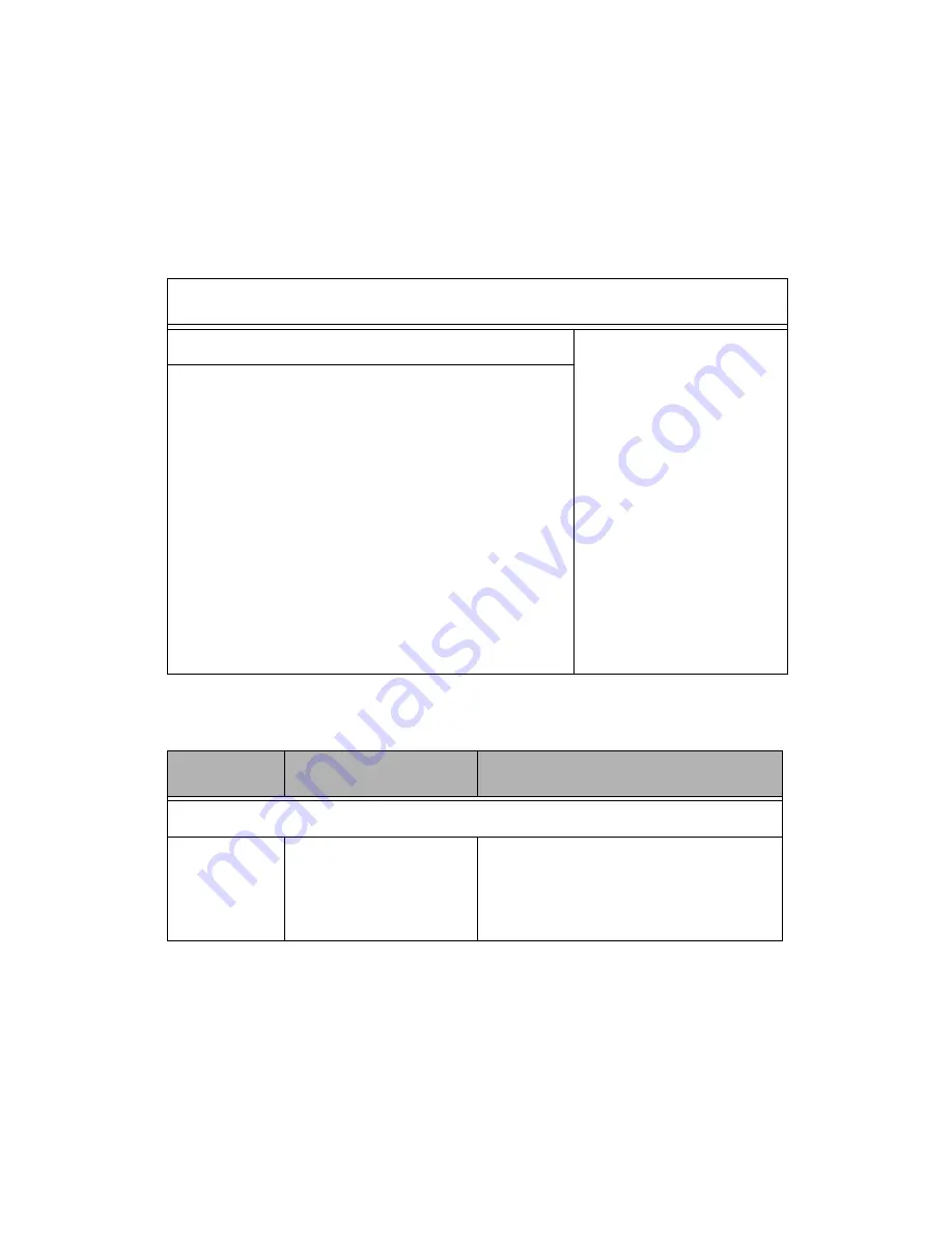
Removable drives submenu
Main
Advanced
PCI/PnP
Boot
Security Chipset Exit
Removable Drives
Use [Enter], [TAB] or
[SHIFT_TAB] to select
a field
Use [+] or [-] to config-
ure system time.
Select Screen
Select item
+/- Change option
Tab Select field
F1 General Help
F10 Save and Exit
ESC Exit
1st Drive
[1st FLOPPY DRIVE]
Feature
Option
Description
Removable Drives
1st Device
1st FLOPPY DRIVE
Disabled
Specifies the boot sequence for
removable drive booting. This
option will show all removable
devices


