5
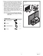
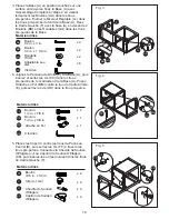
Fig. 5
FF
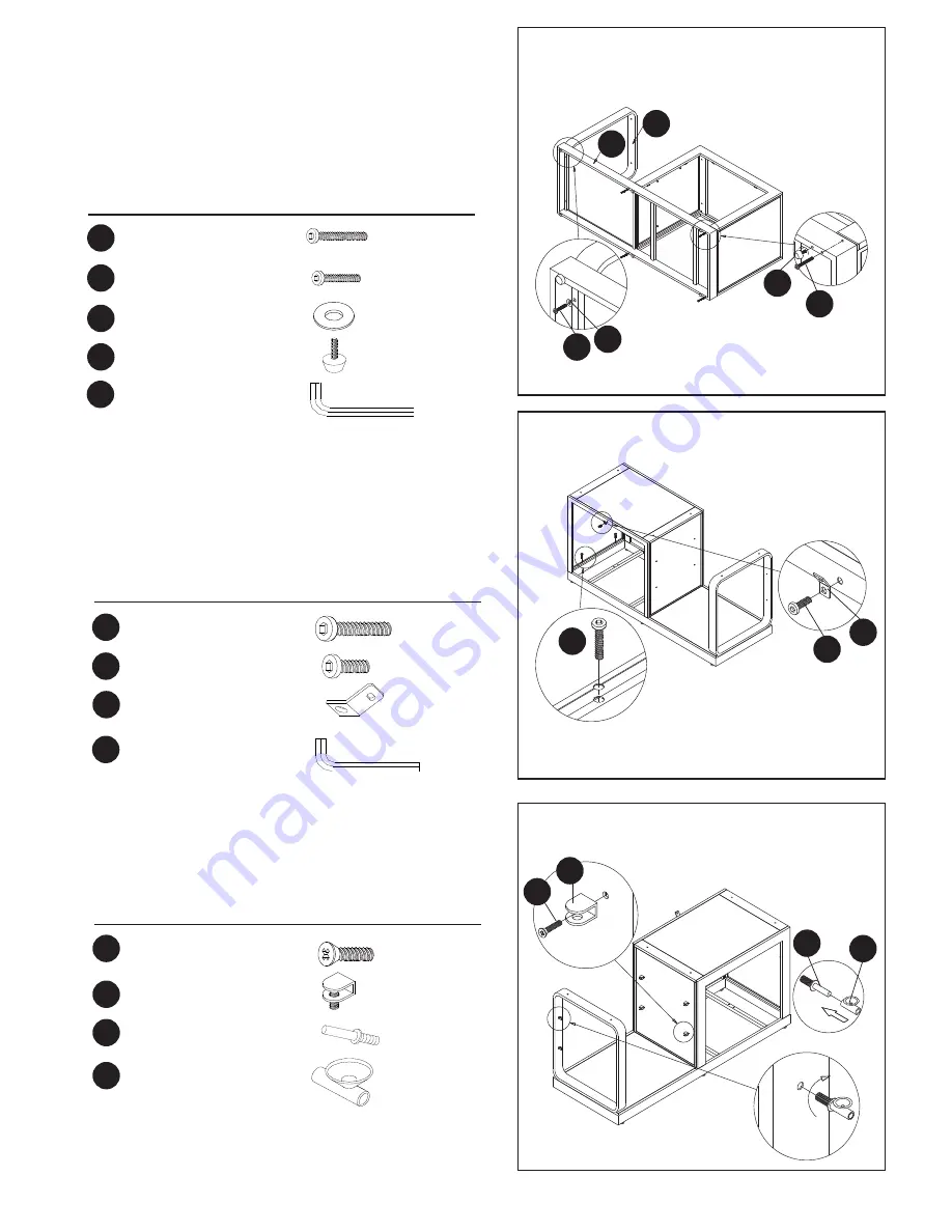
II-1
JJ
KK
Fig. 3
Fig. 4
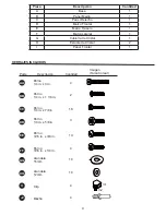
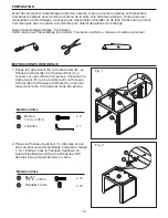
Hardware Used
Hardware Used
Hardware Used
AA
KK
CC
BB
JJ
DD
GG
II
FF
LL
MM
MM
x 4
x 4
x 2
x 4
x 2
x 4
x 4
x 6
x 1
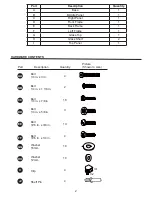
Bolt
1/4 in. x 3 in.
Bolt
1/4 in. x 1 1/8 in.
Washer
16mm
Clip (II-1,II-2)
Bolt
3/16 in. x 1/4 in.
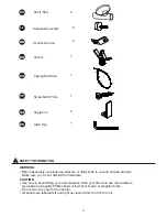
Adjustable Lev-
eler
Connection iron
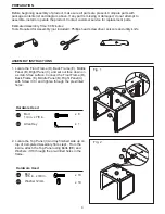
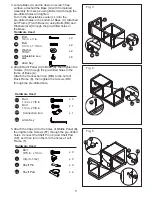
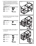
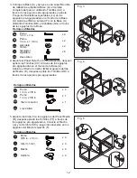
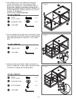
3. Locate Base (A) and lie down on scratch free
surface, attached the Base (A) with Completed
Assembly from step 2 using Bolts (AA) through the
pre-drilled holes and tighten.
Turn in the Adjustable Leveler (LL) into the
pre-drilled holes in the bottom of Base (A). Attached
Left Frame (F) with Base (A) using Bolts (BB) and
Washers (GG) through the pre-drilled holes in
the Base.
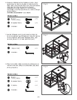
4. Attach Right Panel (C) to Base (A), then tighten the
Screws (CC) through the pre-drilled holes in the
frame of Base (A).
Attach the Connection Iron (MM) to the hole of
Back Frame (E), then tighten the Screws (DD)
through the pre-drilled hole.
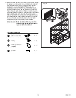
5. Attach the Clips (II) to the holes of Middle Panel (B),
then tighten the Screws (FF) through the pre-drilled
holes. Connect the Shelf Pin (JJ) and Shelf Pad
(KK), and then turn in them to the holes of Left
Frame (F).
Shelf Pad
Shelf Pin
F
A
BB GG
LL
AA
RR
RR
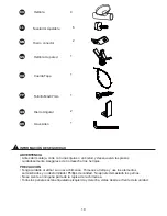
Allen Key
Allen Key
CC
x 4
Bolt
1/4 in. x 7/8 in.
DD
x 1
Bolt
1/4 in. x 5/8 in.


