


20 |E
t
wall
®
Compact32
stationary | User Manual Rev. 1.0
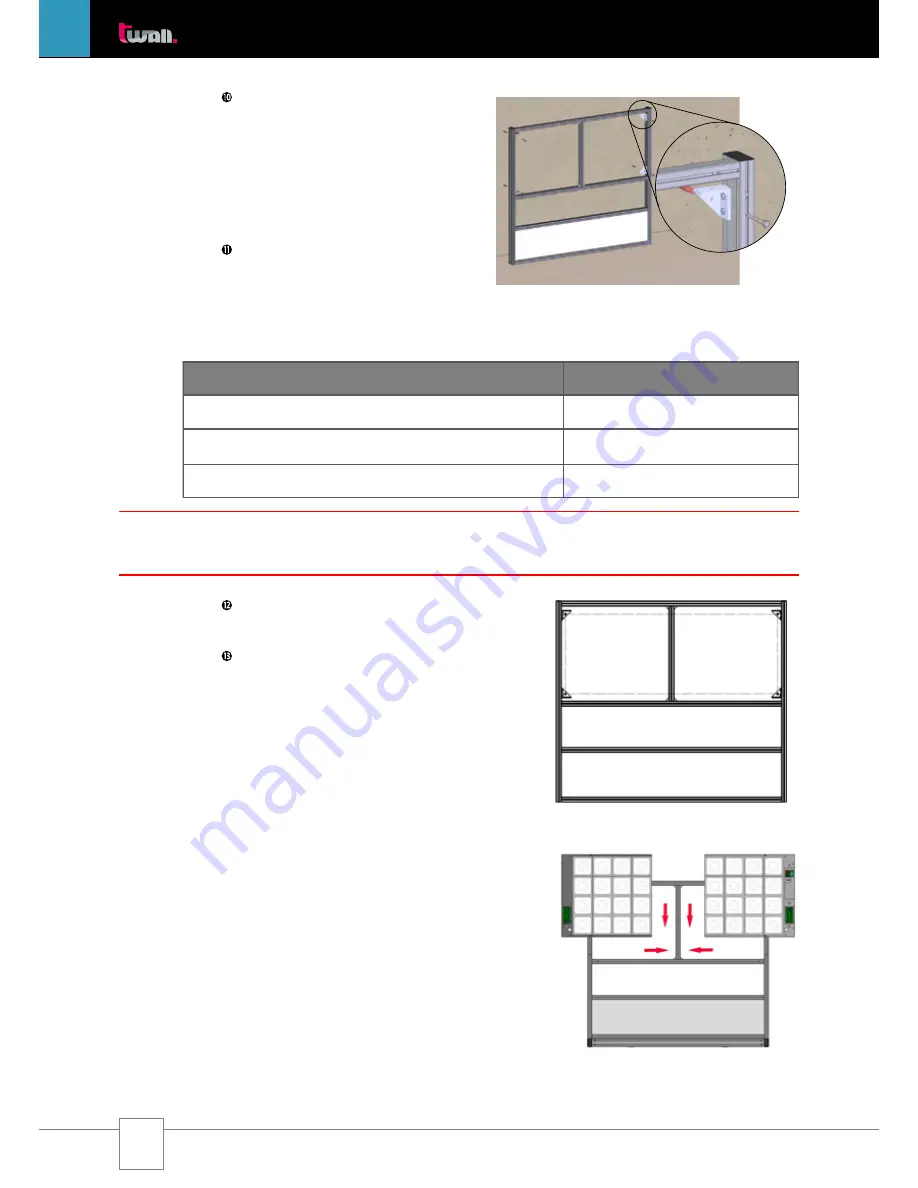
Step
10
The brackets
A2f
are now also
attached to the top guide grooves on the
insides of the side stands
(Fig. 3.2-12)
. To
do this, please use 2 M8x20
Verbus-Ripp
screws
per bracket and tighten these firmly
(approx. 25 Nm).
IV. Assembling the universal wall:
Step
11
To be able to mount the universal
wall to a wall, you need a hammer drill, a
12 mm
impact drilling machine and
appropriate protective gear. The following
boreholes must be made in the wall:
Distances at the wall
t
wall
®
Compact32
stationary
Floor to centre of bottom borehole:
950 mm
Centre of bottom borehole to centre of top borehole
700 mm
Horizontal distance between borehole centres
1863 mm
Step
12
Insert the dowels supplied into the
boreholes in the wall.
Step
13
Lift the universal wall
A2
(Fig.
3.2-13)
at the top end (near the protective
cover) and place it straightened with the
bottom part against the wall. Now attach
the universal wall frame to the wall while
firmly screwing on the brackets
A2f
with
the 4 hexagon head cap wood screws in
the prepared dowels. When using a torque
spanner, adjust it to 25 Nm.
3.2.2.2 Assembling the touch pads
I. Attaching the touch pads:
(Fig. 3.2-14)
Please proceed exactly as described for the
mobile
t
wall
®
Compact32
(Chapter 3.1.3.3)
.
II. Connecting the touch pads with the
control unit:
Please proceed exactly as described for the
mobile
t
wall
®
Compact32
(Chapter 3.1.3.3)
.
NOTE: At least a double covering must be provided with gypsum cardboard walls. The secureness of the
mounting must be checked on a regular basis.
Fig. 3.2-14
Fig. 3.2-13
Fig. 3.2-12
Содержание Compact 32 stationary
Страница 2: ......


