5
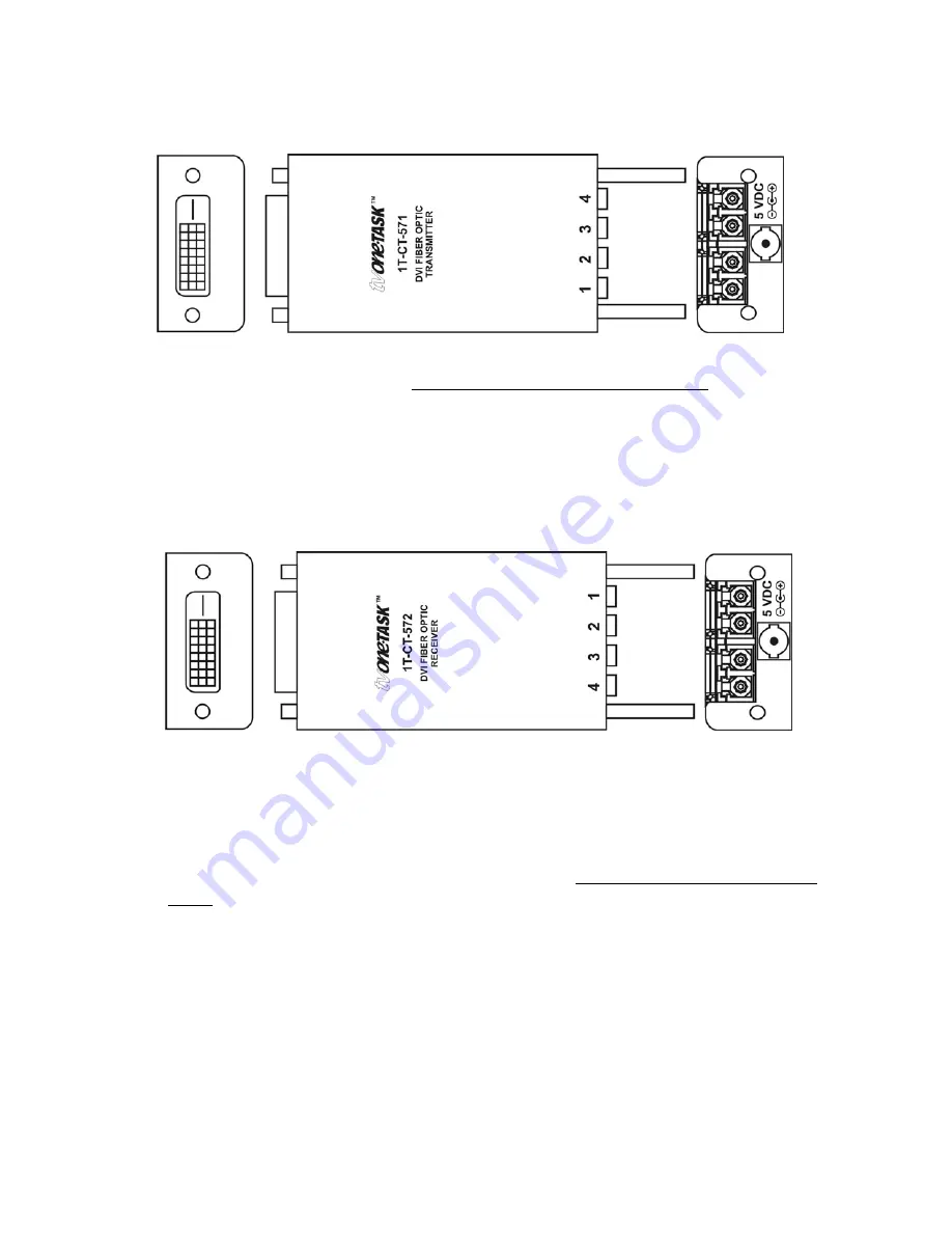
4.2 1T-CT-571
Transmitter
1. Connect the source device’s video output directly and securely to the DVI IN
connector of the Transmitter. DO NOT use an intermediate cable.
2. Connect 4 ea. Fiber Optic cables to the type 4-LC connectors on the
Transmitter.*
* It is recommended that you label each Fiber Optic cable at both ends so that you
can be certain of connecting them correctly.
4.2 1T-CT-572
Receiver
1. At the remote location, connect the other end of the Fiber Optic cables to the
type 4-LC connectors on the Receiver. (Make certain that cable 1 is attached to
the cable 1 connector on both ends and each of the remaining cables is attached
to the same numerical connector on both ends,)
2. Connect the DVI OUT connector of the Receiver directly and securely to the
video input of the remote display or other device. DO NOT use an intermediate
cable.
3. Connect the DC power supply to the Receiver and then to the AC outlet.*
4. Turn on the source device and remote display. The source signal should now
appear on the remotely located display. If not, consult the Troubleshooting
section of this manual.
*The PC should be capable of supplying power to the Transmitter via the DVI-D
connector. For this reason, do not connect the Transmitter’s DC power supply initially. If
the system does not function properly, you should connect an external power supply to
the Transmitter as explained in the next section.
Содержание 1T-CT-570 Series
Страница 1: ...Instruction Manual 1T CT 570 Series Fiber Optic DVI Extender...
Страница 2: ......


