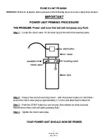
background image


TP9KAC-TUX 

Mar 2019 

1. 

Before proceeding, double check measurements and make certain that the bases of each column are 

square and aligned with the chalk line. 

2. 

Assemble the uprights to the columns. Raise the columns to a vertical position. 

(See Fig. 6)


Fig. 6 

3. 

Using the base plate on the MAIN column as a guide, drill each anchor hole into concrete using a rotary 

hammer drill and 

3

/

4

” concrete drill-bit. To assure full holding power, do not ream the hole or allow the 

drill to wobble. 

(See Anchoring Details on Page 4) 


4. 

After drilling, remove dust thoroughly from each hole using compressed air and/or wire brush. Make 

certain that the column remains aligned with the chalk line during this process. 

5. 

Assemble the washers and nuts on the anchors then tap into each hole with a block of wood or rubber 

hammer  until  the  washer  rests  against  the  base  plate.  Be  sure  that  if 

shimming is required that enough threads are left exposed.


6. 

Using a level, check column plumb for every side 

(Fig. 7)

. If shimming is 

required, use supplied Shim stock or 3/4

” washers, placing shims as close as 

possible to the hole locations. This will prevent bending column bases. 

7. 

With the shims and anchor bolts in place, tighten by securing the nut to the 

base then turning 2-3 full turns clockwise. Ensure anchor bolts are 

tightened to a minimum of 130 ft-lbs. of torque. DO NOT use an impact 

wrench for this procedure!! 

  Fig. 7 


STEP 5

:   

(Installing OFFSIDE COLUMN & OVERHEAD BEAM ASSEMBLY) 


NOTE: Install Overhead Beam assembly to top of columns BEFORE drilling anchors for Offside 

column. This is to ensure that the Offside column can be properly positioned to be plumb and level. 


1. 

Raise OFFSIDE column and position at the designated chalk locations, ensuring the

 Column 

‘upright’ 

Содержание TP9KAC-TUX

Страница 1: ...Mar 2019 TP9KAC TUX Two Post Clear Floor Lift Asymmetric 9 000 lbs Capacity 2 250 lbs Max per Arm INSTALLATION OPERATION MANUAL...

Страница 2: ...rt of the vehicle Improper use of this equipment could result in damage to the lift yourself or other property The lift is intended to lift vehicles only It is not designed to lift any person or equip...

Страница 3: ...Locking Needle Nose and Snap Ring Pliers GENERAL INFORMATION 1 Carefully remove the crating and packing materials CAUTION Be careful when cutting steel banding material as items may become loose and f...

Страница 4: ...TP9KAC TUX Mar 2019...

Страница 5: ...ecting Site Before installing your new lift check the following 1 LIFT LOCATION Always use architects plans when available Check layout dimension against floor plan requirements making sure that adequ...

Страница 6: ...ig 3 Swing Arm Column Layout Fig 4 Column Floor Layout 2 OVERHEAD OBSTRUCTIONS The area where the lift is located should be free of overhead obstructions such as heaters building supports electrical l...

Страница 7: ...tensions hardware box hoses etc from the column Check the quantity of each item with the parts list If anything is missing please contact your dealer at once STEP 3 Site Layout 1 Determine which side...

Страница 8: ...with a block of wood or rubber hammer until the washer rests against the base plate Be sure that if shimming is required that enough threads are left exposed 6 Using a level check column plumb for eve...

Страница 9: ...mns Equal values will ensure the lifting arms will be in square 5 Secure OFFSIDE column to the floor following the same procedures as outlined in STEP 4 STEP 6 Installing POWER UNIT 1 Attach the power...

Страница 10: ...hat each cable has equal tension Also check the carriage height to ensure both carriages are sitting on the same latch STEP 8 Installing Routing HYDRAULIC HOSES HYDRAULIC FITTINGS 1 Install connect th...

Страница 11: ...ymmetric Lifts the short asymmetric swing arms are designed for front vehicle placement with the long asymmetric arms for rear vehicle placement 2 Install arm restraint mechanisms to each swing arm as...

Страница 12: ...mit wire to the eye bolt located on the offside column s upright secure with wire clamp Then carefully route the loose end thru the eye bolt on mainside column s upright and down to the overhead limit...

Страница 13: ...ydraulic system 2 To lower the lift both carriage s safety latch releases must be manually pulled down to be released to lower lift Fig 15 The latches will automatically reset once the lift ascends ap...

Страница 14: ...es and drop into each latch stop 8 Press lowering release lever on Power Unit to lower lift onto latches to lock the lift in the proper safety position Note Always lock the lift before going under the...

Страница 15: ...king Prior to lowering vehicle walk around the lift and check for any objects that might interfere with the operation of lift and safety latches tools air hoses shop equipment After lowering lift swin...

Страница 16: ...k and tighten anchors bolts nut and screws Check wiring switches for damage Keep base plate free of dirt grease or any other corrosive substances Check floor for stress cracks near anchor bolts Check...

Страница 17: ...s for deformation or damage Check cylinder mount for looseness and damage Relocating or changing components may cause problems Each component in the system must be compatible an undersized or restrict...

Страница 18: ...lift B Bad capacitor call electrician C Low voltage call electrician D Faulty wiring call electrician 5 Lift jerks going up and down A Air in hydraulic system raise lift all the way to top and return...

Страница 19: ...TP9KAC TUX Mar 2019 POWER UNIT PRIMING WARNING Failure to properly relieve pressure in the following steps can cause injury to personnel...

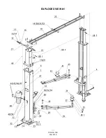
Страница 20: ...TP9KAC TUX Mar 2019 EXPLODED VIEW 1...

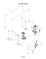
Страница 21: ...TP9KAC TUX Mar 2019 EXPLODED VIEW 2...

Страница 22: ...TP9KAC TUX 017 TPF4A 700 02 03 Spindle 2 18 TP9KAC TUX 018 TPF4A 700 03 01 00 Overhead Beam LH 1 19 TP9KAC TUX 019 GB5781 86 Bolt 4 20 TP9KAC TUX 020 GB6170 86 Nut 4 21 TP9KAC TUX 021 GB93 87 Spring W...

Страница 23: ...T 6934 500 07 Valve Insert 2 55 2 TP9KAC TUX 055 2 TT 6934 500 08 Valve Spring 2 56 TP9KAC TUX 056 TPF4 200 01 00 Carriage 2 57 TP9KAC TUX 057 DL38G C109A Sliding Rub Block 16 58 TP9KAC TUX 058 GB91 8...

Страница 24: ...sidered a warranty issue and therefore must be noted for any potential recovery with the shipping company The customer is required to notify Tuxedo of any missing parts within 72 hours Timely notifica...

Отзывы: