Operator’s Manual 2020 0217 ENG
16
06
Disassembly and Reassembly
5. Use jacking screws on the end plate from
the housing. The rotors will be removed from
the housing when the gear end end plate is
removed. Use a gear puller and attach to the
gear end plate with the center of the puller in
the center of the rotor shaft. Apply pressure,
pushing the rotor away from the end plate.
Repeat this process until both rotors have
been removed. Remove the inner sleeve of the
seal housing from the rotor shafts with a puller.
Inspect and clean the seal area on the rotor
shaft.
6. Remove the bearings, seal housing, slingers,
bearing shield, and bearing shims from end
plate. Use a hammer and bar to drive the
bearing and seal housing from the end plates.
Inspect the bearing wear pattern and seal for
wear and heat marks. Clean all parts before
inspecting. Check the rotor bearings for
proper spinning. Check the seal
fi
ts of the seal
housing on the rotor shaft. Check the bearing
bores and seal bores in the end plate for
spinning of bearings and seal housings.
ASSEMBLY
The components in
Table 6-1
are available as a
kit from Tuthill Vacuum & Blower Systems. These
components are replaced during a normal blower
overhaul. These parts, at minimum, should be on
hand prior to assembly.
DESCRIPTION
QTY
Bearing
2
Bearing
2
Bearing Shield
2
Seal Assembly
4
Gasket
2
Drive Shaft Seal
1
O-Ring
2
Port Gasket
2
Timing Adjustment Shim
1
Bearing Shim
8
Table 6-1 – Overhaul Kit
Gear End Assembly
1. Check all parts to make sure the parts are
clean and free of burrs or nicks that may
have occurred when the blower was being
disassembled. Check the repair kit for the
correct parts needed to complete the assembly
of the unit. Make sure you have the proper
tooling and training required to assemble the
blower. Take the time to read and completely
understand the instruction manual before you
begin.
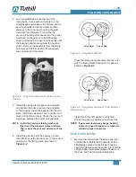
2. Seat the rotors on a
fi
xture with the gear end
of the rotors upward and in the “T” position, as
shown in
Figure 6-2
. Place a set of 0.006 in.
shims on each rotor. Make sure the drive rotor
is in the correct location for the proper
fl
ow and
rotation required for the application.
DRIVE
DRIVEN
Figure 6-2 – Correct Positioning of Rotor Keyways for
Assembly
OTE:
N
Use Loctite thread sealant on all bolts and
capscrews that are assembled without
lock washers.
3. Install the end plate onto the rotor. Make sure
the shims on the rotor are still in place. Using
a seal pressing tool (see
Figure 8-1
for detail),
press the seal assembly onto the rotor shafts.
Press the oil shield onto the rotor shafts.
OTE:
N
The oil shield is part of the seal assembly
but must be pressed on after the seal
assembly is installed. On lip seal units,
the seal must be pressed into the seal
housing after the end plates have been
installed onto the housing and before the
slinger is installed on the rotor shaft.


