


Czujnik magneto-indukcyjny
do detekcji nakrętek M6
with TIN coating
NIMFE-EM12/4,9L88-UP6X-H1141/S1182
Edition
•
2014-04-17T05:24:26+02:00
3 / 4
Hans Turck GmbH & Co.KG
ñ
D-45472 Mülheim an der Ruhr
ñ
Witzlebenstraße 7
ñ
Tel. 0208 4952-0
ñ
Fax 0208 4952-264
ñ
ñ
www.turck.com
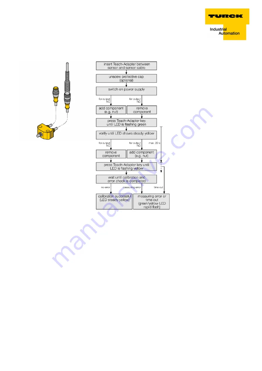
Parameterisation with the teach adapter:
The measuring signal in the sensor is influenced by the
diameter and the material characteristics of the center
bolt, but also by the cover of the sensitive area. There-
fore each sensor has to be conditioned to the operating
environment, i.e. to the applied sleeves or protective
caps and the target (nut, sleeve etc.) In order to calibra-
te a sensor, the teach adapter VB2-SP1 made by Turck
is needed.
Error display
If the output is in switch-on state and the error messa-
ges 'overload' i.e. 'short circuit' are signaled, the output
is immediately switched off. Within one second the sen-
sor checks if the state of short circuit still remains, if not,
the output is switched-on again. The states of 'overload'
or 'short circuit' are signaled yellow by the LED with 1
Hz. Each sensor monitors the internal signals and har-
dware components. The output is switched-off by the
following errors:
- Interruption of the sensor signal (e.g. by a magnetic
field)
- Excess temperature (internal device temperature
>100°C)
- Defective hardware
Sensor errors are indicated by alternate flashing gre-
en and yellow LEDs. The sensor errors are usually self-
resetting, i.e. the sensor changes automatically to the
normal operating state, after the error was corrected.
After switching on the operating voltage the sensor
checks its operating parameters. If errors occur during
the checking process, the sensor remains in the error
state (green LED blinking). The output cannot be swit-
ched-on in this state. A new calibartion with the teach
adapter is required.


