Product description
Functions and operating modes
Hans Turck GmbH & Co. KG | T +49 208 4952-0 | [email protected] | www.turck.com
V03.00 | 2022/08 | 9
4.2
Properties and features
n
Measurement lengths from 100…2000 mm
n
Shock-proof up to 200 g
n
Maintains linearity under shock load
n
Immune to electromagnetic interference
n
5-kHz sampling rate
n
16-bit resolution
4.3
Operating principle
The Li-Q25L linear position sensors have contactless operation based on the inductive resonant
circuit measuring principle. Measuring is immune to magnetic fields as the positioning element
is not based on a magnet but on a coil system. Sensor and positioning element form an induct-
ive measuring system. An induced voltage generates appropriate signals in the receiver coils of
the sensor, depending on the location of the positioning element. The signals are evaluated in
the internal 16-bit processor of the sensor and output as analog signals.
4.4
Functions and operating modes
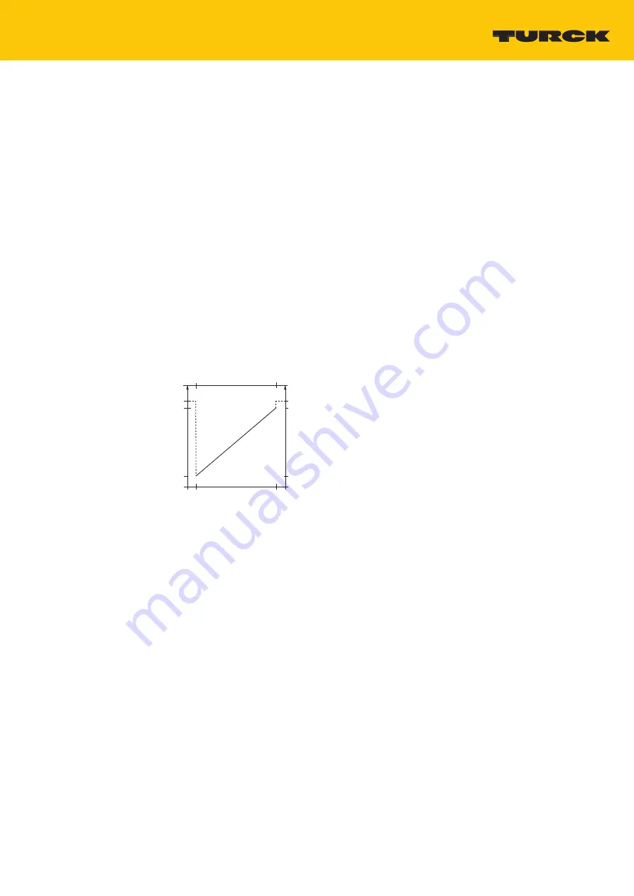
The devices feature a current and voltage output. The device provides a current and voltage
signal at the output proportional to the position of the positioning element.
A
I [mA]
U [V]
0
B
A
B
4
10
11
20
24
Fig. 3: Output characteristics
4.4.1
Output function
The measuring range of the sensor starts at 4 mA or 0 V and ends at 20 mA or 10 V. Current and
voltage output can be used simultaneously. Current and voltage outputs can be used simultan-
eously for functions such as redundant signal evaluation. In addition, one display unit can re-
ceive a signal while the second signal is processed by a PLC.
In addition to the LEDs, the sensor offers an additional control function. If the positioning ele-
ment is outside the detection range and the coupling between the sensor and the positioning
element is interrupted, the analog output of the sensor outputs 24 mA or 11 V as a fault signal.
This error can therefore be evaluated directly via the higher-level control.


