background image


28                                                  SERVICE  MANUAL  FOR  AMERICA


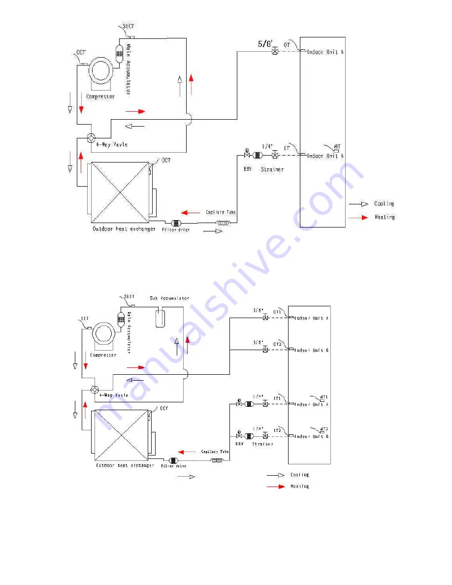
9 . 4     T A S - 1 8 M V H / O     R e f r i g e r a t i o n  D i a g r a m


9 . 5  T A S - 2 4 M V H / O     R e f r i g e r a t i o n  D i a g r a m


Содержание TAS-09EH/O

Страница 1: ...n Unit TAS 09EH O TAS 12EH O TAS 18EH O TAS 24EH O TAS 24MVH O TAS 18MVH O Indoor Unit Outdoor Unit TAS 09MVH TAS 18MVH O TAS 24MVH O TAS 12MVH TAS 09EH TAS 09EH O TAS 12EH TAS 12EH O TAS 18EH TAS 18EH O TAS 24EH TAS 24EH O REFRIGERENT HEAT PUMP R410A SERVICE MANUAL ...

Страница 2: ...ATING CONDITIONS 3 1 4 OUTLINE DIMENSIONS 4 1 5 PERFORMANCE DATA 5 1 6 PRESSURE CURVES 6 1 7 ELECTRICAL DATA 7 1 8 WIRING DIAGRAMS 8 1 9 REFRIGERATION DIAGRAMS 9 1 10 TUBING CONNECTIONS 10 1 11 CONTROL SYSTEM 11 1 12 TROUBLESHOOTING 12 1 13 EXPLODED VIEWS AND SPARE PARTS LISTS 13 1 14 APPENDIX A ...

Страница 3: ...s inverter compressor driver high speed calculation for accurate sine wave form vector control smart PFC control fuzzy logic control High SEER Lego Concept Pre Charged Cooling operation at outdoor temperature down to 500 F Heating operation at outdoor temperature down to 50 F Variable Speed outdoor fan Low noise level EEV for each indoor unit 1 3 Tubing Connections Flare type interconnecting tubin...

Страница 4: ...ion L M H CFM 212 270 315 341 382 430 441 530 618 518 588 677 Indoor Noise level dB A L M H 42 38 35 42 38 35 50 47 44 50 47 44 Outdoor Fan Speed RPM 100 900 100 900 100 900 100 900 Outdoor Noise Level dB A 57 57 57 57 Indoor Fan Speeds 950 1150 1300 750 900 1000 950 1100 1230 1080 1180 1280 Connection Method Flare Flare Flare Flare Max Pipe Length Ft 82ft 25m 82ft 25m 82ft 25m 82ft 25m Max Elevat...

Страница 5: ... 4 450 VAC 4 450 VAC Fan Motor FLA A 0 98 0 98 Fan Speed RPM 900 750 500 900 750 500 Outdoor Fan Fan Type Axial Axial Fan Blade Diameter in 18 1 18 5 Air Flow Volume of Outdoor Unit CFM M 3 h 2800 3200 Compressor Model C 6RZ146H1A C 7VRN153HOW TYPE DC DC Brand Sanyo Sanyo Capacity W 6420 7110 Input W 1635 1770 Condenser Number of Rows 2 26 2 26 Tube Pitch x Row Pitch 1 x 866 in 1 x 866 in Fin spac...

Страница 6: ...W x H x D in 33 86 x 13 78 x 10 43 Net Gross Wt lbs 26 45 30 86 Dehumidifying Volume pt hr 1 8 Auto restart YES 2 2 2 TAS 12MVH Specifications Indoor TAS 12MVH FAN MOTOR Model YDK 16 4C Input W 54 Capacitor UFD 1 2 450VAC Fan Motor FLA A 0 25 Speed Hi Med Low RPM 1200 950 850 Cooling 1200 950 750 Heating Evaporator Number of rows 22 Tube pitch row pitch in 69 50 Fin spacing in 0 059 Fin Type Louve...

Страница 7: ...ng Indoor 80o FDB 67o F WB Outdoor 95o F DB 75o F WB Heating Indoor 70 o F DB 60 o F WB Outdoor 47o F DB 43 o F WB 3 1 Operating Limits Outdoor Cooling Upper limit DB 110 o F Lower limit DB 5o F Heating Upper limit DB 75 o F Lower limit DB 5o F Voltage 2PH 198 264V 115V 3PH N A 4 OUTLINE DIMENSIONS 4 1 outdoor Unit TAS 09EH O ...

Страница 8: ...8 SERVICE MANUAL FOR AMERICA 4 2 outdoor Unit TAS 12EH O 4 3 outdoor Unit TAS 18EH O 4 4 outdoor Unit TAS 24EH O ...

Страница 9: ...9 SERVICE MANUAL FOR AMERICA 4 5 outdoor Unit TAS 18MVH O ...

Страница 10: ...ndoor Units Data 5 1 1 Indoor Units Capacity For 9000BTU Capacity Model 9000BTU TAS 09MVH TAS 09EH 5 1 1 1 Cooling Capacity BTU Run Model Unit A B C or D 230 115V Indoor fan at high speed INDOOR ENTERING AIR DB WB TEMPERATURE 0 F OUTDOOR ENTERING AIR DB TEMPERATURE 0 F DATA 72 59 75 63 81 66 84 70 90 73 14 68 TC 80 110 of nominal ...

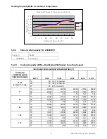
Страница 11: ... 0 86 0 87 0 88 0 89 0 91 L E G E N D TC Total Cooling Capacity BTU SC Sensible Capacity BTU PI Power Input kW WB Wet Bulb Temp 0 F DB Dry Bulb Temp 0 F ID Indoor OD Outdoor 5 1 1 2 Heating Capacity BTU Run Model Unit A B C or D 230 115V Indoor fan at high speed ID COIL ENTERING AIR DB TEMPERATURE 0 F OD COILENTERING AIR DB WB TEM PERATU RE 0 F DATA 59 68 77 5 3 TC 6912 6372 5940 PI 0 49 0 54 0 59...

Страница 12: ... Ratio Vs Outdoor Temperature Cooling Capacity Correction Factor 0 0 2 0 4 0 6 0 8 1 1 2 1 4 77 86 95 104 115 Outdoor Temp deg F Capacity Ratio 90 73 84 70 81 66 75 63 72 59 Heating Capacity Ratio Vs Outdoor Temperature Heating Capacity Correction Factor 0 0 2 0 4 0 6 0 8 1 1 2 1 4 5 14 20 30 36 45 50 59 Outdoor Temp deg F Capacity Ratio 59 68 77 ...

Страница 13: ...ge TC 80 110 of nominal SC 80 105 of nominal PI 25 50 of nominal 77 TC 11616 12336 13104 13872 14640 SC 10421 10603 10845 11027 11269 PI 0 72 0 73 0 75 0 76 0 77 86 TC 11040 11808 12576 13296 14064 SC 10118 10361 10542 10785 10966 PI 0 81 0 82 0 83 0 85 0 86 95 TC 10464 11232 12000 12768 13536 SC 9876 10058 10300 10542 10724 PI 0 88 0 90 0 92 0 93 0 94 104 TC 9936 10704 11424 12192 12960 SC 9634 9...

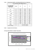
Страница 14: ...91 0 97 1 04 30 28 TC 11060 10500 9800 PI 0 96 1 02 1 08 36 34 TC 11340 10640 10080 PI 0 99 1 06 1 12 45 43 TC 14560 14000 13440 PI 1 04 1 11 1 18 50 48 TC 15400 14840 14140 PI 1 11 1 18 1 25 59 54 TC 16240 15680 14980 PI 1 16 1 22 1 30 59 75 Protection Range TC 85 105 of nominal PI 80 120 of nominal 5 2 1 3 Capacity Correction Factors Cooling Capacity Ratio Vs Outdoor Temperature Cooling Capacity...

Страница 15: ...PERATURE 0F DATA 72 59 75 63 81 66 84 70 90 73 14 68 protection range TC 80 110 of nominal SC 80 105 of nominal PI 25 50 of nominal 77 TC 17424 18504 19656 20808 21960 SC 15480 15750 16110 16380 16740 PI 1 19 1 21 1 23 1 25 1 27 86 TC 16560 17712 18864 19944 21096 SC 15030 15390 15660 16020 16290 PI 1 34 1 36 1 38 1 40 1 42 95 TC 15696 16848 18000 19152 20304 SC 14670 14940 15300 15660 15930 PI 1 ...

Страница 16: ...40 1 50 30 28 TC 15010 14250 13300 PI 1 39 1 46 1 56 36 34 TC 15390 14440 13680 PI 1 42 1 52 1 62 45 43 TC 19760 19000 18240 PI 1 50 1 60 1 70 50 48 TC 20900 20140 19190 PI 1 60 1 70 1 80 59 54 TC 22040 21280 20330 PI 1 68 1 76 1 87 59 75 Protection Range TC 85 105 of nominal PI 80 120 of nominal 5 2 3 3 Capacity Correction Factors Cooling Capacity Ratio Vs Outdoor Temperature Cooling Capacity Cor...

Страница 17: ...PERATURE 0F DATA 72 59 75 63 81 66 84 70 90 73 14 68 protection range TC 80 110 of nominal SC 80 105 of nominal PI 25 50 of nominal 77 TC 23232 24672 26208 27744 29280 SC 20640 21000 21480 21840 22320 PI 1 72 1 75 1 78 1 81 1 84 86 TC 22080 23616 25152 26592 28128 SC 20040 20520 20880 21360 21720 PI 1 93 1 96 1 99 2 02 2 05 95 TC 20928 22464 24000 25536 27072 SC 19560 19920 20400 20880 21240 PI 2 ...

Страница 18: ...98 2 12 30 28 TC 19355 18375 17150 PI 1 96 2 07 2 20 36 34 TC 19845 18620 17640 PI 2 01 2 15 2 29 45 43 TC 25480 24500 23520 PI 2 12 2 26 2 40 50 48 TC 26950 25970 24745 PI 2 26 2 40 2 54 59 54 TC 28420 27440 26215 PI 2 37 2 48 2 65 59 75 Protection Range TC 85 105 of nominal PI 80 120 of nominal 5 2 4 3 Capacity Correction Factors Cooling Capacity Ratio Vs Outdoor Temperature Cooling Capacity Cor...

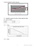
Страница 19: ...city Correction Factor 0 0 2 0 4 0 6 0 8 1 1 2 1 4 5 14 20 30 36 45 50 59 Outdoor Temp deg F Capacity Ratio 59 68 77 5 3 Capacity Correction Factor Due to Tubing Length One Way 5 3 1 Indoor units Model TAS 09MVH TAS 12MVH TAS 09EH TAS 12EH TAS 18EH TAS 24EH 5 3 1 1 Cooling 5 3 1 2 Heating ...

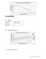
Страница 20: ...20 SERVICE MANUAL FOR AMERICA 6 Pressure Curve 6 1 Model TAS 09EH O TAS 18MVH O TAS 12EH O TAS 24MVH O TAS 18EH O TAS 24EH O 6 1 1 Suction Pressure Curve 6 1 2 Discharge Pressure Curve ...

Страница 21: ...connecting cable No x cross section 2 X 4 X 1 mm2 Model TAS 12EH O Power Supply 1 PH 115 VAC 60Hz Connected to Outdoor Maximum Current 10 8A Inrush Current 40A Starting Current 1A Circuit breaker 30A Power supply wiring No x cross section 1 X 3 X 2 5 mm2 Interconnecting cable No x cross section 2 X 4 X 1 mm2 Model TAS 18EH O Power Supply 1 PH 230 VAC 60Hz Connected to Outdoor Maximum Current 10 1A...

Страница 22: ...5A Inrush Current 40A Starting Current 1A Circuit breaker 20A Power supply wiring No x cross section 1 X 3 X 2 5 mm2 Interconnecting cable No x cross section 2 X 4 X 1 mm2 Model TAS 24MVH O Power Supply 1 PH 230 VAC 60Hz Connected to Outdoor Maximum Current 13A Inrush Current 35A Starting Current 1A Circuit breaker 30A Power supply wiring No x cross section 1 X 3 X 2 5 mm2 Interconnecting cable No...

Страница 23: ...23 SERVICE MANUAL FOR AMERICA 8 WIRING DIAGRAMS 8 1 TAS 09EH O Wiring Diagram 8 2 TAS 12EH O Wiring Diagram ...

Страница 24: ...24 SERVICE MANUAL FOR AMERICA 8 3 TAS 18EH O Wiring Diagram 8 4 TAS 24EH O Wiring Diagram 8 5 TAS 18MVH O Wiring Diagram ...

Страница 25: ...25 SERVICE MANUAL FOR AMERICA 8 6 TAS 24MVH O Wiring Diagram 8 4 TAS 18MVH O TAS 24MVH O Indoor Outdoor Wiring Diagram ...

Страница 26: ...26 SERVICE MANUAL FOR AMERICA 8 5 TAS 09EH O TAS 12EH O TAS 18EH O TAS 24EH O Indoor Outdoor Wiring Diagram 9 REFRIGERATION DIAGRAMS ...

Страница 27: ...27 SERVICE MANUAL FOR AMERICA 9 1 TAS 09EH O Refrigeration Diagram 9 2 TAS 12EH O Refrigeration Diagram 9 3 TAS 18EH O TAS 24EH O Refrigeration Diagram ...

Страница 28: ...28 SERVICE MANUAL FOR AMERICA 9 4 TAS 18MVH O Refrigeration Diagram 9 5 TAS 24MVH O Refrigeration Diagram ...

Страница 29: ...29 SERVICE MANUAL FOR AMERICA 10 TUBING CONNECTIONS ...

Страница 30: ...above the outdoor no trap is required 11 CONTROL SYSTEM T U B E I n c h T O R Q U E N m F l a r e N ut s 11 13 40 45 60 65 70 75 80 85 Va l ve C a p 13 20 13 20 18 25 18 25 40 50 Service Port Cap 11 13 11 13 11 13 11 13 11 13 1 Valve Protection Cap end 2 Refrigerant Valve Port use Allen wrench to open close 3 Valve Protection Cap 4 Refrigerant Valve 5 Service Port Cap 6 Flare Nut 7 Unit Back Side ...

Страница 31: ...t temperature 5 O F 185 O F relative humidity 30 95 2 Receive distance of remote 10m 3 Angle of remote 120 degree 4 Control precision of temperature 1 8 O F 5 Speed precision of indoor fan motor 10RPM 6 Time precision 0 1 三 Major function of control 1 Remote Turn on off Mode select auto cooling dehumidify heating ventilation Indoor fan speed select manual mode high middle low speed auto mode accor...

Страница 32: ... red turbo running green economic running Indoor temperature control Coil pipe of indoor unit overheat protection Coil pipe of indoor unit anti frost protection Sleep Swing Anti cold air in heating mode Indoor fan motor protection Fault display DC Inverter 1 1 24000BTU mode high middle low Cooling speed 1280 1180 1080 Heating speed 1280 1180 1080 18000BTU mode high middle low Cooling speed 1230 10...

Страница 33: ...duce power if indoor room temp continuous less than set temp for 5 minutes Air blow function indoor blower fan continuous running 20 seconds at low speed after air conditioner turn off in cooling mode if the flap is swing shutdown the flap after turn off indoor blower fan Indoor blower fan can select one of four speed Fan speed is determined by the difference of room temp and set temp in auto wind...

Страница 34: ...n speed is determined by the difference of room temp and set temp in auto wind but anti cold wind is prior speed high middle low 0 O F 4 O F 6 O F 9 O F ΔT Anti cold wind When air conditioner first power on or change mode indoor blower fan didn t running When the coil pipe temp of indoor unit is more than 86 O F start turnning on indoor blower fan lower speed if the coil pipe temp of indoor unit d...

Страница 35: ...ning mode If it auto select is cooling mode and other indoor unit is running heating mode then it select ventilation mode If it auto select is heating mode but other indoor unit is running cooling mode display error of mode clash if it select is ventilation mode then it running is ventilation 5 Ventilation 1 Range of set temp 60 O F 90 O F 2 Indoor blower fan is operate same as cooling mode 3 Flap...

Страница 36: ...is use in cooling heating ventilation mode the indoor blower fan is running at super speed 1 enter condition press turbo key of remote 2 end condition running time more than or equal to 15 minutes press turbo key of remote again 3 all restrict and protect condition are active in turbo running 4 return to prior state after end turbo running 五 Protection 1 Prevent frost of indoor coil pipe cooling a...

Страница 37: ...urn off power on or receive remote signal 八 Display 1 After turn on air conditioner mode clash display d1 and timer lamp flash light one second extinguish one second defrost display dF the running lamp flash light one second extinguish one second indicate anti cold wind when air conditioner is normal running the running lamp is light 2 Set timer or sleep the yellow lamp is light 3 Outdoor unit and...

Страница 38: ...ressor min EV Indoor temp 87 OF Compressor mid 2 Heating Condition Entering Method label Capacity Pressing Tubro for 5 times Setting temp 77 O F H01 Pressing Tubro for 5 times Setting temp 79 O F H11 Pressing Tubro for 5 times Setting temp 81 O F H12 Pressing Tubro for 5 times Setting temp 83 O F H22 Pressing Tubro for 5 times Setting temp 85 O F H32 Pressing Tubro for 5 times Setting temp 87 O F ...

Страница 39: ...GB T7725 2004 GB4706 32 2000 三 Input Output of Outdoor Controller 1 Outputs of one three phase Frequency Conversion two relays one indicator led and one communication signal 1 Controlling the three phase output of compressor 2 Controlling the output of outdoor motor 3 Controlling the output of 4 way valve 4 Controlling the output of communication signals of indoor unit 5 Controlling the output of ...

Страница 40: ...ter the expansion valve step and its adjust cycle shall be adjusted according to the difference in temperature between the inlet and outlet of evaporator Control of compressor s frequency 1 Range of compressor s frequency Fmin Fmax Fmin the lowest frequency Fmax the highest frequency 2 Frequency decrease protection of compressor frequency decrease protection is prior during frequency adjustment of...

Страница 41: ...the basic step and can t adjust Ten minutes later the expansion valve step and its adjust cycle shall be adjusted according to the difference in temperature between the inlet and outlet of evaporator Control of compressor s frequency Range of compressor s frequency Fmin Fmax Fmin the lowest frequency Fmax the highest frequency Control of fan motor in heating mode figure 5 1 The fan motor of outdoo...

Страница 42: ...g in heating mode the time is clear and it judge whether outdoor coil pipe temp and outdoor ambient temp satisfy defrost condition if the frequency of compressor is 25HZ and satisfy defrost condition then if enter defrost process After end defrost process or over 10 minutes it return normal running 2 Defrost end condition 1 T盘 b O F b is a adjust constant or defrost time more than or equal to c mi...

Страница 43: ...de or dehumidify with heating mode together the outdoor unit operate state is decided by the indoor unit which is applied first 十 Protect function 1 Delay protection of compressor The compressor can t run after it stop within 3 minutes 2 Fault protection of module The air conditioner stop running immediately and display error code if the module is fault 3 Protection of communicate fault The contro...

Страница 44: ...pipe more than 134 O F 3 It resume normal frequency when the temp of middle coil pipe less than133 O F 8 High temp protection of indoor coil pipe 1 The compressor decrease frequency until the temp of indoor coil pipe more than Tsce 2 if the temp of indoor coil pipe less than Tsce 2 in cooling mode The compressor decrease frequency until the temp of indoor coil pipe less than Tsce 2 if the temp of ...

Страница 45: ...cy when the input current less than or equal to Imax 20 13 DC voltage of wire protection 1 The air conditioner stop running and display DC voltage abnormal when it less than 260V 2 The compressor decrease frequency and display FA6 when DC voltage less than 285V 3 The air conditioner resume normal running when DC voltage more than 290V 十一 Outdoor unit fault of indoor unit display fault display Tran...

Страница 46: ...ired F2 1 Temp sensor of indoor room short or cut off change sensor F3 1 Temp sensor of indoor coil pipe outlet short or cut off change sensor 2 Temp sensor of indoor coil pipe entrance short or cut off change sensor 3 Temp sensor of indoor coil pipe middle short or cut off change sensor F4 1 PG motor fault change motor PG 2 Fixed screw loose fix cross flow fan 3 Communication interfere earth wire...

Страница 47: ...itch of compressor cut off 4 Communication interfere earth wire can t with communicate wire in same cable check cable P7 1 PFC board fault change PFC board 2 Communication of main board and PFC board fault check wires of main board and PFC board P8 1 Less refrigerant add refrigerant 2 Coil pipe sensor can t contact with coil pipe 3 4 way valve fault change 4 way vavle fault ...

Страница 48: ...ont Plate 1 12 阀座板 Valve installation plate 1 3 轴流风轮 Axial flow fan 1 13 低压阀 Low pressure valve 1 4 电 机 Motor 1 14 高压阀 Ligh pressure valve 1 5 电机支架 Motor support 1 15 毛细管组件 Capillary Assy 1 6 冷凝器 Condenser 1 16 电子膨胀阀 Electronic expansion valve 1 7 顶盖板 Top panel 1 17 四通阀组件 Four way valve assembly 1 8 电控盒 Electric box 1 18 压缩机 Compressor 1 9 背网 Rear Grill 1 19 中隔板 Partition board 1 10 右侧板 Right pane...

Страница 49: ...ar Grill 1 14 底盘 Base 1 4 中隔板 Partition board 1 15 冷凝器 Condenser 1 5 四通阀 Four way valve 1 16 电机支架 Motor support 1 6 电子膨胀阀 Electronic expansion valve 1 17 电机 Motor 1 7 干燥过滤器 Desiccation filter 1 18 轴流风机 Axial flow fan 1 8 右侧板 Right panel 1 19 前网罩 Front Grill 1 9 大抽手 Large handle 1 20 前面板 Front Plate 1 10 阀座板 Valve installation plate 1 21 左护网 Left protect net 1 11 低压阀 Low pressure valve 1 22 左侧板 Lef...

Страница 50: ...nic expansion valve 1 3 轴流风轮 Axial flow fan 1 13 右侧板 Right panel 1 4 电 机 Motor 1 14 电器盒盖 Top of the Electric Box 1 5 左侧板 Left panel 1 15 阀座板 Valve installation plate 1 6 电机支架 Motor support 1 16 低压阀 Low pressure valve 1 7 冷凝器 Condenser 1 17 高压阀 High pressure valve 1 8 顶盖板 Top panel 1 18 维修板 Maintenance plate 1 9 电器盒 Electric box 1 19 压缩机 Compressor 1 10 背网 Rear Grill 1 20 中隔板 Partition board 1 21 底...

Страница 51: ...essor 1 4 电控盒 Electric box 1 16 底盘 Base 1 5 四通阀 Four way valve 1 17 冷凝器 Condenser 1 6 干燥过滤器 Desiccation filter 1 18 电机支架 Motor support 1 7 电子膨胀阀 Electronic expansion valve 1 19 电机 Motor 1 8 右侧板 Right panel 1 20 轴流风机 Axial flow fan 1 9 电器盒盖 Top of the Electric box 1 21 前网罩 Front Grill 1 10 阀座板 Valve installation plate 1 22 前面板 Front Plate 1 11 低压阀 Low pressure valve 1 23 左护网 Left protect net 1 12 高...

Страница 52: ...alve 1 4 左侧板 Left panel 1 17 A 机 DN10 截止阀 DN10 valve 1 5 电机支架 Motor support 1 18 B 机 DN4 截止阀 DN4 valve 1 6 冷凝器 Condenser 1 19 B 机 DN10 截止阀 DN10 valve 1 7 顶盖板 Top panel 1 20 维修板 Maintenance plate 1 8 电器盒 Electric box 1 21 干燥过滤器 Desiccation filter 1 9 背网 Rear Grill 1 22 压缩机 Compressor 1 10 汽液分离器 Steam liquid segregator 1 23 中隔板 Partition board 1 11 四通阀组件 Four way valve assembly 1 24 底盘 Base 1 12 电子膨...

Страница 53: ... Left protect net 1 17 A 机 DN10 截止阀 DN10 valve 1 5 电机支架 Motor support 1 18 B 机 DN4 截止阀 DN4 valve 1 6 立 柱 Pillar 1 19 B 机 DN10 截止阀 DN10 valve 1 7 顶盖板 Top panel 1 20 维修板 Maintenance plate 1 8 冷凝器 Condenser 1 21 小抽手 Small handle 2 9 中隔板 Partition board 1 22 干燥过滤器 Desiccation filter 1 10 电器盒 Electric box 1 23 压缩机 Compressor 1 11 四通阀组件 Four way valve assembly 1 24 油汽分离器 Oil and steam separator 1 12 电子膨...

Страница 54: ...54 SERVICE MANUAL FOR AMERICA APPENDIX A APPENDIX A INSTALLATION AND OPERATION MANUAL I NSTALLATI ON MANUAL CMV ...

Страница 55: ...e the system so it operates safely and efficiently For safe installation and trouble free operation you must Carefully read this instruction booklet before beginning Follow each installation or repair step exactly as shown Observe all local state and national electrical codes Pay close attention to all danger warning and caution notices given in this manual WARNING This symbol refers to a hazard o...

Страница 56: ... may be suspended from a wall by a bracked Optional or located in a free standing position on the floor preferably slightly elevated 3 If the unit is suspended ensure that the bracket is firmly connected and the wall is strong enough to withstand vibrations 4 Unit location should not disturb neighbours with noise or exhaust air stream 5 Place the mounting pads under the unit legs 6 Refer to figure...

Страница 57: ...d voltage 1 Remove the power supply cable that is connected to the indoor unit 2 To connect the indoor units to the outdoor units use the following electrical cables Electrical connections Power input cable 1 group 3 wiresX2 5mm2 cable between indoor and outdoor units 1 group 4 wiresX 1 0mm2 see Fig 6 7 8 9 10 for detail 3 Prepare the cable ends for the power input and for the cables between outdo...

Страница 58: ... do not use the existing piping because there are some problems with presure fittings and possible impurities in existing piping Changes in the product and components In air conditioners using R410A in order to prevent any other refrigerant from being accedentally charged the service port diameter size of the outdoor unit control valve 3 way valve has been changed 1 2 UFN 20 threads per inch In or...

Страница 59: ...ent vacuum pump oil from flowing back into the charge hose The charge hose connecting part has two ports one for conventional refrigerant 7 16 UNF 20 theads per inch and one for R41 OA if Gas leakage detector x Exclusive for HFC refrigerant Incidentally the refrigerant cylinder comes with the refrigerant designation R410A and protector coating in the U S s ARI specified rose color Ari color code P...

Страница 60: ...e flare nuts that are mounted on the supplied outdoor and indoor units 4 Connect the all ends of the tubing to the indoor and outdoor units Notice the sign All ends should correspond one by one 5 Insulate each tube separately and their unions with at least 6mm thick of insulation Wrap the refrigerant tubing drain hose and electric cables together with a vinyl tape UV protected Fig 11 1 INDOOR UNIT...

Страница 61: ...um pump 3 Open Fully the low and high pressure sides of the manifold gauge valves 4 Turn on the vacuum pump Perform evacuating for at least 30 minutes and than confirm that the needle in the gauge moves from 0 MPa Ocm Hg t0 0 1 MPa 76cm Hg 5 Close the valves of the low and high sides of the charging set and turn off the vacuum pump After few minutes if the gauge needle has moved there is a leak wh...

Страница 62: ...ensure that they had tightened properly Close the valve cover 2 Fill gaps on the wall between hole sides and tubing with sealer 3 Attach wiring and tubing to the wall with clamps where necessary 4 Operate the unit for no less than 5 minutes at heating or cooling mode 5 Explain filter removal cleaning and installation 6 Operate the air conditioner together with the customer and explain all function...

Отзывы: