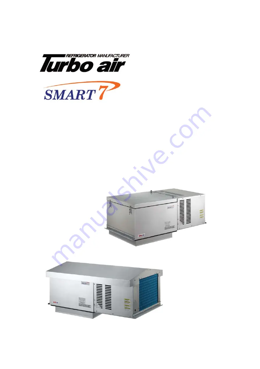
Turbo Air SMART 7 STI022LR404A2 Скачать руководство пользователя страница 1

Turbo air Speeds Up the Pace of Innovation 


Part No. KUCST1307 

               CAREL CONTROLLER


Refrigeration System 

Installation & Operation Manual 

Please read this manual completely before attempting to install or operate this equipment ! 


Package Unit ( TOP MOUNT ) 


Содержание SMART 7 STI022LR404A2

Страница 1: ...the Pace of Innovation Part No KUCST1307 CAREL CONTROLLER Refrigeration System Installation Operation Manual Please read this manual completely before attempting to install or operate this equipment Package Unit TOP MOUNT ...

Страница 2: ...2 ...

Страница 3: ... CONTENTS Safety Information 4 Inspection 4 Locating SMART 7 Package Unit 7 Installation Procedure 9 Sequence of Operation 11 Controller Setting 12 System Troubleshooting 25 Electrical Wiring Diagram 26 ...

Страница 4: ...any or trained personnel when you installing moving operating of the unit Field wiring must confirm to the requirements of units electric specification Inspection A person at the job site to receive material holds responsibility Each shipment should be carefully inspected against the bill of lading The shipping receipt should not be signed before careful inspection Check carefully for concealed da...

Страница 5: ... 7395 5406 4002 208 230 3 60 13 3 20 R404A 46 NO 318 C STI070LR404A2 9139 7520 5439 208 230 1 60 19 8 30 R404A 46 NO 320 C STI070LR404A3 9139 7520 5439 208 230 3 60 13 9 20 R404A 46 NO 317 C Table 3 OUTDOOR UNIT Medium Temperature Air Defrost System Model Ambient 95 Voltage MCA MOPD Refrigerant Plug Supplied Matching NEMA Receptacle NET Weight Lbs Fig Capacity BTUH Ref Wt oz 35 38 STI050MR404A2 50...

Страница 6: ... Figure B INDOOR UNIT Medium Cabinet Opening Size 25 inch x 25 inch Figure C INDOOR UNIT Large Cabinet Opening Size 25 inch x 38 5 inch Figure D OUTDOOR UNIT Medium Cabinet Opening Size 25 inch x 25 inch Figure E OUTDOOR UNIT Large Cabinet Opening Size 25 inch x 38 5 inch ...

Страница 7: ...aintenance must be carried out by licensed contractor in conformity with the local standard construction code Ignoring above requirement will result in system fault shorten life span and void the warranty Unit Transport Requirements 1 Do not remove shipping skid until ready to move it upon box rooftop 2 Always watch out not to contact sharp edges and coil surfaces to avoid potential injury Wear sa...

Страница 8: ...8 Figure 1 Minimum Clearance at Installation of Unit W UNIT WIDTH Figure 2 One Unit W UNIT WIDTH Figure 3 Two or more Unit ...

Страница 9: ...ed opening with the evaporator air flow directly forward the door and ensure the grill not to damage during installation 8 Secure that the condenser airflow is not obstructed 9 Drain is not needed as condensate is vaporized by hot gas lines in the drain panel from the compressor discharge 10 Install trim pieces around the open on the ceiling of box Outdoor use only STX Model Installation is the sa...

Страница 10: ...d refrigerant connections 2 Check all wiring and insulators 3 Check contactors for proper operation and for state of contact points 4 Check all fan motor Tighten motor mount bolts nuts and fan set screws 5 Clean the heatexchanger evaporator and condenser coil surface 6 Check the operation of the control system Make sure all safety controls are operating properly 7 Check the defrost control system ...

Страница 11: ...nergized and re operated Operation of Defrost 1 Under normal electric defrost operation the temperature defrost control will de energize the compressor contactor evaporator fans and energize the defrost heaters But under normal air defrost operation the control will de energize the compressor contactor and keep an evaporator fan motor working 2 When the coil has defrosted completely and reached th...

Страница 12: ...damage the system separate as much as possible the probes and digital input signal cables from the cables carrying inductive loads and power cables to avoid possible electromagnetic disturbance Never lay power cables including the electrical cables and probe signal cables in the same conduits Do not install the probe cables in the immediate vicinity of power devices contactors circuit breakers or ...

Страница 13: ...isplays sets the set point more than 3 s accesses the parameter setting menu enter password 22 mutes the audible alarm buzzer for 1 s RESET current EZY set Pressed together 2 and 3 activate parameter reset procedure 3 more than 3 s activates deactivates the defrost pressed together with 1 activates deactivates the continuous cycle for 1 s displays firmware version Preliminary configurations Once t...

Страница 14: ... display and setting alarms E0 E1 E2 the internal timer relating to parameter dI is updated If dI expires in OFF status a defrost is performed when restarting auxiliary relay management only in the following configurations H1 1 2 E0 alarm only H1 3 A4 6 WARNINGS when first connected easy is already on and ready to be used the instrument can be switched on from a supervisor PC and via an external c...

Страница 15: ...e useful for rapidly bringing the temperature below the set point value Rapid display of the temperature read by the other probes Press the DOWN button to scroll the temperatures read by the probes Each time the DOWN button is pressed the display will show the name of the probe Pr1 Pr2 or Pr3 only on the models with 3 inputs and with multifunction input configured as a probe and after 1 s the temp...

Страница 16: ...4 Defrost on power up 0 1 1 dd Dripping time 0 15 2 F0 Enable evaporator fan control 0 1 0 F2 Stop evaporator fan if compressor stop 0 1 0 F3 Evaporator fan status during defrost 0 1 1 Fd Post dripping time 0 15 2 Table 6 SET 2 EZY 3 Medium temperature SET POINT 38 Air defrost Parameter Description Min Max Default St Set point 0 50 38 r1 Minimum set point value 50 50 0 r2 Maximum set point value 0...

Страница 17: ...e buzzer and alarm relay LED alarm description reset enable alarm parameters involved E0 active on probe 1 error control automatic E1 not active on probe 1 error defrost automatic d0 0 1 4 F0 1 E2 not active on probe 1 error condenser product automatic A4 10 IA active on external alarm automatic A4 1 A7 dOr active on open door alarm automatic A4 7 8 A7 LO active on low temperature alarm automatic ...

Страница 18: ...er alarms are active or the second probe is displayed E1 flashing evaporator probe or food conservation probe error probe not working the probe signal is interrupted or short circuited probe not compatible with the instrument E2 flashing condenser probe or food conservation probe error probe not working the probe signal is interrupted or short circuited probe not compatible with the instrument IA ...

Страница 19: ...s when the next defrost ends correctly dF flashing defrost running this is not an alarm signal but rather a message that the instrument is running a defrost Only shown if d6 0 cht flashing dirty condenser pre alarm check parameters A4 Ac AE and Acd CHt flashing dirty condenser alarm check parameters A4 Ac AE and Acd EtC flashing internal clock error Data error In certain operating conditions the i...

Страница 20: ...that need to be modified press the SET button for more than 3 s to permanently save the parameters and exit the parameter setting procedure Accessing the type C parameters press the SET button for more than 3 s if there are active alarms mute the buzzer the display shows the parameter code PS password press the SET button to access the password setting use the UP and DOWN buttons to scroll the num...

Страница 21: ...egory of parameters Category Initial Icon Category Initial Icon Probe parameters Alarm parameters A Control parameters r Fan parameters F Compressor parameters c AUX output configuration parameters H1 Defrost parameters d RTC parameters Setting the default parameters WARNINGS running this procedure overwrites any custom parameter settings To reset the default parameters disconnect power from the i...

Страница 22: ...temperature is too high parameters dt and d defrost probe the manual defrost is not activated and the defrost LED flashes compressor protection times set parameter d9 select d9 1 the high temperature alarm is shown after a defrost the alarm delay after defrost is too short or the alarm threshold is too low parameters d8 and AH the display remains frozen even after the defrost the ambient temperatu...

Страница 23: ...tive compressor starts C 0 100 min 0 0 c2 minimum compressor off time C 0 100 min 4 4 c3 minimum compressor on time C 0 100 min 0 0 c4 compressor on time with duty setting C 0 100 min 0 0 cc continuous cycle duration C 0 15 hours 4 4 c6 temperature alarm bypass after continuous cycle C 0 15 hours 2 2 d DEFROST PARAMETERS d0 type of defrost 0 heater by probe 1 hot gas by probe 2 heater by time 3 ho...

Страница 24: ...lay C 0 199 Min 0 0 A8 enable alarm Ed end defrost by timeout 1 enabled C 0 1 0 0 Ac high condenser temperature alarm C 50 250 150 150 AE high condenser temperature alarm differential C 0 1 20 0 10 10 Acd high condenser temperature alarm delay C 0 250 min 0 0 F FAN PARAMETERS F0 fan management 0 fans on 1 controlled based on parameter F1 C 0 1 0 0 F1 evaporator fan control set point F 50 130 5 5 F...

Страница 25: ...protector switch open Evaporator dirty or iced Clean and defrost Condenser coil dirty Clean coil Too much refrigerant Remove excess refrigerant Clogged liquid line filter drier Replace filter drier Operating beyond design conditions Add facilities so that conditions are within allowable limits Fan s will not operate Main swich open Close switch Blown fuses Replace fuses Check for short circuits or...

Страница 26: ...26 Electrical Wiring Diagram Diagram 1 Wiring diagram for SMART 7 Air Defrost 115V 1Ph 60Hz Model STI030MR404A1 Diagram 2 Wiring diagram for SMART 7 Air Defrost 115V 1Ph 60Hz Model STI050MR404A1 ...

Страница 27: ...ring diagram for SMART 7 Air Defrost 208 230V 1Ph 60Hz Model STI050MR404A2 STX050MR404A2 Diagram4 Wiring diagram for SMART 7 Air Defrost 208 230V 1Ph 60Hz Model STI068MR404A2 STI075MR404A2 STX068MR404A2 STX075MR404A2 ...

Страница 28: ...or SMART 7 Air Defrost 208 230V 1Ph 60Hz Model STI100MR404A2 STI130MR404A2 STX100MR404A2 STX130MR404A2 Diagram6 Wiring diagram for SMART 7 Air Defrost 208 230V 3Ph 60Hz Model STI100MR404A3 STI130MR404A3 STX100MR404A3 STX130MR404A3 ...

Страница 29: ...agram7 Wiring diagram for SMART 7 Electric Defrost 208 230V 1Ph 60Hz Model STI022LR404A2 STX022LR404A2 Diagram8 Wiring diagram for SMART 7 Electric Defrost 208 230V 1Ph 60Hz Model STI045LR404A2 STX045LR404A2 ...

Страница 30: ...RT 7 Electric Defrost 208 230V 1Ph 60Hz Model STI055LR404A2 STI070LR404A2 STX055LR404A2 STX070LR404A2 Diagram10 Wiring diagram for SMART 7 Electric Defrost 208 230V 3Ph 60Hz Model STI055LR404A3 STI070LR404A3 STX055LR404A3 STX070LR404A3 ...

Страница 31: ...31 1250 Victoria street CARSON CA 90746 FAX 310 900 1008 Toll Free 888 900 1002 U S A Canada http www turboairinc net ...

Отзывы: