background image


13 


ASSEMBLY

ASSEMBLY

ASSEMBLY

ASSEMBLY    

GEAR

GEAR

GEAR

GEARBOX

BOX

BOX

BOX ASSEMBLY

 ASSEMBLY

 ASSEMBLY

 ASSEMBLY    

 
1.  Press  the  bearings  (20)  onto  the 

worm  (44)  then  install  the  worm  and 
bearings into the housing (39).  


2. 

For winches driven by a hydraulic 
motor: 

Press  a  new  oil  seal  (19)  into  the 
motor adapter (60).  Attach the motor 
adapter (60) to the housing (39) with 
six  capscrews  (80),  using  gasket 
(11).    Install  the  motor  (57)  with  two 
capscrews (58) and washers (61).


For  winches  driven  by  a  PTO 
sprocket and chain: 

Press a new oil seal (19) into the end 
cap (45).  Attach the end cap (45) to 
the  housing  (39)  with  six  capscrews 
(18) using gasket (11).   
 

3.  Install  the  keys  (36)  into  the  output 

shaft (37). 


4.  Bolt  the  gear  (28)  to  the  carrier  (40) 

using  twelve  capscrews  (35),  nuts 
(12), and washers (13). 

 
5.  Install  the  assembled  gear  onto  the 

shaft (37).  Press the roll pin (41) into 
the  carrier  (40).    Slide  the  bushings 
(21)  on  to  both  ends  of  the  output 
shaft (37). 

 
6.  Install  the output  shaft  ass’y  into  the 

housing (39). 

 
7.  Attach  the  cover  (26)  to  the  housing 

(39),  using  capscrews  (24  and  25), 
nuts  (12),  washers  (13),  using 
gaskets (27). 

 
8.  Fill  the  gearbox  and  brake  with  the 

proper oil.  Refer to the maintenance 
section of this manual for oil type and 
amount. 


Содержание RUFNEK 10

Страница 1: ...SSEMBLY 9 RUFNEK 15 BRAKE DISASSEMBLY 9 MODEL 10 BRAKE DISASSEMBLY 10 CLUTCH AND DRUM DISASSEMBLY 11 GEARBOX DISASSEMBLY 11 GEAR INSPECTION INSTRUCTIONS 12 ASSEMBLY 13 GEARBOX ASSEMBLY 13 MODEL 10 BRA...

Страница 2: ...ed by a qualified person All welding should also be done by a qualified person Winch mount must be flat so as not to induce binding The flatness must not exceed 1 16 inch across the mounting surface o...

Страница 3: ...ch is fully engaged before hoisting A visual inspection of the drum clutch engagement is required before each winching operation Must rig all loads secure before winching Pull the load line taut and i...

Страница 4: ...ries designation number will be issued for the winch A new manual will also be created for that specific design series WINCH BREAK WINCH BREAK WINCH BREAK WINCH BREAK IN IN IN IN Winches like any othe...

Страница 5: ...pe 1 Single Speed Gear Motor 2 Two Speed Gear Motor 3 Single Speed Geroler Motor 4 Two Speed Geroler Motor 5 Piston 6 Vane X No Motor RN15 W M R F O M X Winch Type M Mechanical H Hydraulic No of Worm...

Страница 6: ...ormal usage Tulsa Winch recommends that the oil level in the gearbox be checked and adjusted as part of the pre use inspection If the oil level drops frequently or oil leakage is detected during an in...

Страница 7: ...7 OIL LEVELS OIL LEVELS OIL LEVELS OIL LEVELS BRAKE OIL DRAIN BRAKE OIL LEVEL BRAKE FILL VENT GEARBOX OIL LEVEL GEARBOX FILL VENT GEARBOX OIL DRAIN...

Страница 8: ...ten the brake loosen the two capscrews in the slotted holes and rotate the brake in the direction shown If the brake needs to be reversed remove those same two capscrews rotate the cam 60 degrees and...

Страница 9: ...emove the capscrews 75 from the brake cover 77 4 Remove the spring 73 Remove the brake driver 78 along with the brake components 63 64 65 69 74 5 Inspect parts as follows replace if necessary A Inspec...

Страница 10: ...s in the brake drum 17 and a gear puller to remove the brake drum 7 Inspect parts as follows replace if necessary A Inspect the brake shoes 6 for wear If the shoe linings are worn flush with the rivet...

Страница 11: ...removing capscrews 24 and 25 nuts 12 and washers 13 2 Use the hoist to lift the output shaft 37 bushings 21 keys 36 roll pin 41 and gear assembled items 12 13 28 35 and 40 out of the housing 39 3 Rem...

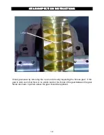
Страница 12: ...TRUCTIONS GEAR INSPECTION INSTRUCTIONS Check gear wear by removing the cover and visually inspecting the bronze gear If the gear is worn such that there is no visible land on the throat of the gear be...

Страница 13: ...in Press a new oil seal 19 into the end cap 45 Attach the end cap 45 to the housing 39 with six capscrews 18 using gasket 11 3 Install the keys 36 into the output shaft 37 4 Bolt the gear 28 to the ca...

Страница 14: ...44 Next install clutch driver assembly 65 69 74 78 onto the coupler 66 3 With the retaining ring 69 on the driver 78 Install the stator plates 63 and friction discs 64 starting with a stator plate an...

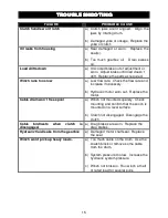
Страница 15: ...rate Check the flow rate and increase if necessary b Hydraulic motor worn out Replace the motor Cable drum won t free spool a Winch not mounted squarely Check mounting and confirm that the winch is m...

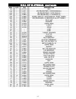
Страница 16: ...1 23875 CAM 16 6 939261 CAPSCREW 17 1 29503 BRAKE DRUM 18 4 28578 CAPSCREW 19 1 20232 SEAL 20 2 20732 BALL BEARING 21 2 20710 BUSHING 22 1 12079 BUSHING 23 3 21128 GREASE ZERK 24 2 20270 CAPSCREW 25...

Страница 17: ...20728 THRUST WASHER 53 1 20712 CLUTCH 54 1 939266 BUSHING 55 1 20716 END BRACKET 56 1 1125 CLUTCH THROWOUT 57a 1 43632 MOTOR RUFNEK 15 57b 1 40272 MOTOR MODEL 10 58 2 13529 CAPSCREW 59 1 40147 GASKET...

Страница 18: ...0 53 42 7 16 20 55 41 33 78 58 47 1 2 13 76 57 45 106 80 64 1 2 20 85 64 51 120 90 72 9 16 12 109 82 65 153 115 92 9 16 18 122 91 73 172 129 103 5 8 11 150 113 90 212 159 127 5 8 18 170 128 102 240 18...

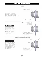
Страница 19: ...19 CLUTCH INSPECTION CLUTCH INSPECTION CLUTCH INSPECTION CLUTCH INSPECTION...

Страница 20: ...20 ISOMETRIC DR ISOMETRIC DR ISOMETRIC DR ISOMETRIC DRAWING AWING AWING AWING FOR RUFNEK BRAKE AND HYDRAULIC MOTOR ASSEMBLIES SEE PAGE 18...

Страница 21: ...TOR VIEWS RUFNEK BRAKE AND HYDRAULIC MOTOR VIEWS RUFNEK BRAKE AND HYDRAULIC MOTOR VIEWS RUFNEK BRAKE AND HYDRAULIC MOTOR VIEWS HYDRAULIC MOTOR RUFNEK BRAKE TWG PO Box 1130 Jenks OK 74037 1130 USA Phon...

Отзывы: