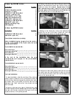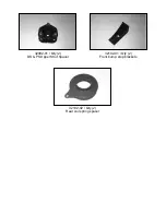
Hardware bag 32102NB includes:
Description
Quantity
32102-03 (Speciality washer)
2
124B (1/2” x 4” bolt)
2
716WA (7/16” USS flat washer)
4
12UN (1/2” unitorque nut)
2
716112B (7/16” x 1 1/2” bolt)
2
38WA (3/8” USS flat washer)
4
716UN (7/16” unitorque nut)
2
516WA (5/16” USS flat washer)
2
38NLN (3/8” nylon nut)
2
PB6052 (poly bump stop)
2
ZIPTIE (Zip tie)
2
Hardware bag D2P-NB includes:
Description
Quantity
516WA (5/16” USS flat washer)
6
38NLN (3/8” nylon nut)
6
Please follow instructions carefully:
Before installation begins, measure from the center of
the hub, to the bottom of the fender well, and record
measurements below.
Pre-installation measurements:
Driver side front:_________________________________
Passenger side front:_____________________________
Driver side rear:__________________________________
Passenger side rear:______________________________
At the end of the installation take the same
measurements and compare to the pre-installation
measurements.
Post-installation measurements:
Driver side front:_________________________________
Passenger side front:_____________________________
Driver side rear:_________________________________
Passenger side rear:______________________________
Front end installation:
1. To begin installation, block the rear tires of the vehicle so
that the vehicle is stable and can’t roll backwards. Safely lift
the front of the vehicle and support the vehicle with a pair of
jack stands. Place a jack stand on both the driver and the
passenger side. Next, remove the front wheels and tires
from both sides.
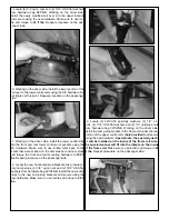
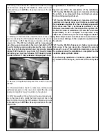
2. Working on the driver side, place a hydraulic floor under
the lower control arm and carefully raise up on the hydraulic
floor jack until it makes contact with the lower control arm.
Repeat procedure on the passenger side.
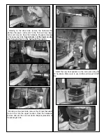
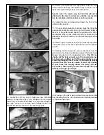
3. Working on the driver side, remove the sway bar end link
hardware that attached the sway bar end link to the lower
control arm. Save the hardware.
Special note: To help
make removal easier, place a wrench or a pair of needle
nose vise grips on the end link so the end link does not
spin.
Repeat procedure on the passenger side.
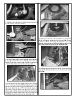
4. Working on the driver side, remove the hardware that
attaches the coil over to the lower control arm. Save the
hardware. Repeat procedure on the passenger side.
5. Working on the driver side, place a reference mark on the
cam washer and cam stops that attach the lower control arm
to the front and rear lower control arm mounts. Repeat pro-
cedure on the passenger side.


