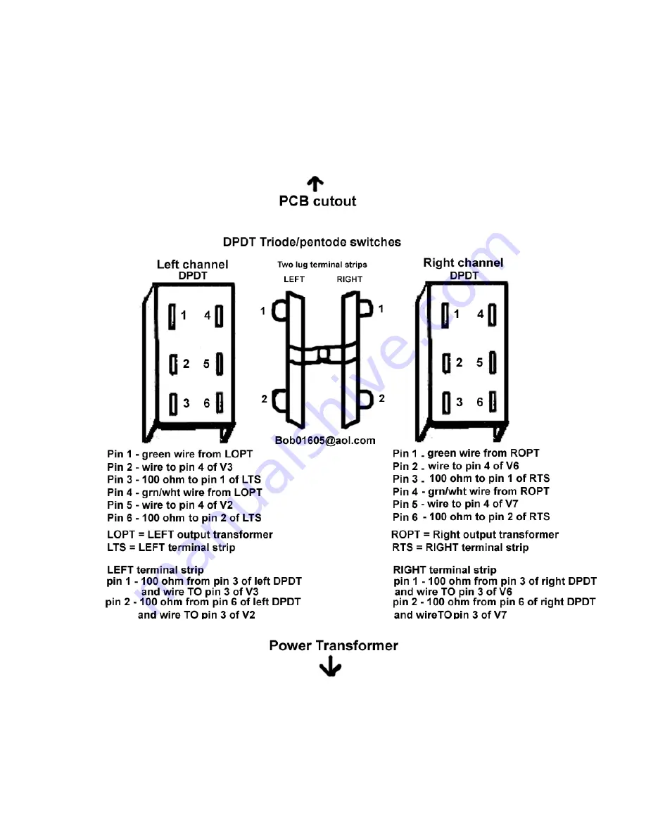
Triode/Pentode switch pictorial
NOTE: Disregard any pin number markings on the switches themselves
and use the pin numbers listed below.
Страница 1: ...with an ESL reduction capacitor Your KIT comes with a very easy to follow instruction manual and a clear pictorial specific to the VTA driver board All you need to complete the kit is a soldering penc...
Страница 2: ...cer s and screw and replace it with one of the six machine screws and nut Tighten the nut securely 3 Do the same for the transformer screw on the opposite diagonal corner of the transformer 4 Remove t...
Страница 3: ...e mounting plates One of the round plastic colored spacers red or black goes INSIDE the chassis and the other spacer with the binding post attached goes OUTSIDE the chassis Make sure that the BLACK te...
Страница 4: ...citors face the power transformer Tighten the two nuts The two SCM caps may touch the chassis This is OK 9 Mount the THREE lug terminal strip on the LEFT side of the chassis with a single 4 40 screw a...
Страница 5: ...ime The 20 gauge tin coated solid core copper wire supplied with this kit is the recommended wire to use Only rosin core solder is recommended for soldering Always make a solid mechanical connection w...
Страница 6: ...0 and 40 Mfd terminals on the quad cap as you did with the right side choke 10 Extend the two BLACK leads from the power transformer around the power transformer as shown in the pictorial Connect one...
Страница 7: ...Triode Pentode switch pictorial NOTE Disregard any pin number markings on the switches themselves and use the pin numbers listed below...
Страница 8: ......
Страница 9: ......