


H-123 consists of ultrasonic sensors, digital control unit and display. This system detects
the distance between the car and back obstruction by the ultrasonic sensors installed at the
rearward of the car. The distance and direction of the back obstruction will be displayed in an
innovative mode with the specially designed LED light, three-step sounds. With changes of
sound and number color, drivers can control the distance between the car and obstruction .
MAIN FEATURES
Led display
Dashboard/front roof installation
Buzzer or display for option
TECHNICAL SPECIFICATIONS
Rated Voltage: DC 12V
Operating Range: DC 9
16V
Operating Current: 20
200mA
Detecting Distance: 0.3
1.5m(Back) 0.3-1.0m(Front)
~
~
~
ALARM MODE
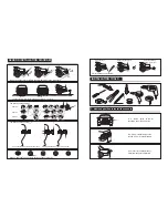
1. Choose right installation position for sensors
2. Select drilling position for sensor A & D
3. Select drilling position for sensor B & C
4. Locate the position and drill
INSTALLATION STEPS
5. Install the sensors and hide the wires
6. Install the display
7. Install the control box
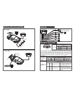
8.Connect the whole system according to
the General Installation Diagram
TEST
1. The car must be in power-off during the installation.
2. Its performance may be affected in following situation: heavy rain, gravel road, bumpy road
sloping road and bush, very cold, hot or moist weather, or the sensor is covered by ice, mud,
etc..
3.
4. The sensors should be installed appropriate loose or tight.
5. Its performance may be effected if the sensors are fixed on metallic bumper.
6. Avoid installing the digital control box in places of great interference, such as vent-pipe, wiring
nearby.
7. Test the system to make sure it works normally before using.
8. This system is a reversing aid and the manufacturer will take no responsibility for any
accident after the kit is installed.
Other ultrasonic or electric wave, the instance of DC/AC switch or 24/12v switch maybe affect
the performance of the system.
NOTE
1. Adjust the directions of sensors and axial orientation, neaten the wiring after installing the
sensors;
2. Connect the red power wire with the positive of reversing light, the black wire with the ground;
3. Connect the display with the digital control box, do not connect the sensors;
4. Put the car into back gear , the display will show radix point which indicate the system is in
test status;
Test: a. If no sound, please check whether the wire is connected correctly, the voltage is larger
than 9V, or the LED is well connected with control unit; b. If there is a BiBi alarm sound,
please switch the power off then enter into the back gear again, if the problems could not be
removed, the control unit could be decided to be failed. The whole system should be
replaced.
5. Test the sensors one by one.
Test: a. When testing some sensor, if the buzzer gives continuous "Bi
…
" sound, please check
whether some parts of the car or some unwanted objects fall into the detecting range, or the
sensor is near to some strong interference sources (such as exhaust pipe, other wires); b. If
there is an alarm sound (Bi
…
Bi
…
) and the display shows distance but there is nothing in
front of the sensor, maybe the sensor is detecting the ground, please check the position and
direction of the sensor; or the sensor maybe detect some parts of the car; c. If the problem
still could not be removed, the whole system should be replaced.
obstruction identification of left and right
Sensitivity adjustable; Anti-hook function
Ultrasonic Frequency: 40KHz
Working Temperature: -30
+70
℃
Display Size: 148*20*17mm
~
Back
System
Stage
Distance
Awareness
Alarm
Sound
Triangle
Display
Alarm
Color
1
>
1
.
5m
Safety
Area
Silence
↓
Extinguish
2
1
.
5
-
1
.
2m
Safety
Area
Bi……Bi……
↓
1Yellow
3
1
.
1
-
0
.
9m
Safety
Area
Bi……Bi……
↓
2Yellow
4
0
.
8m
Alarm
Area
Bi…Bi…
↓
3Yellow
5
0
.
7
-
0
.
6m
Alarm
Area
Bi…Bi…
↓
4Yellow
6
0
.
5
-
0
.
4m
Danger
Area
Bi……
↓
4Yellow
,
1Red
7
<=
0
.
3
Danger
Area
Bi……
↓
4Yellow
,
2Red
Front
System
Stage
Distance
Awareness
Alarm
Sound
Alarm
Color
1
2
3
4
5
6
>
1
.
0m
Safety
Area
Silence
↓
Extinguish
0.9-0
.
8m
Safety
Area
Bi……Bi……
↓
1Yellow
0
.
7m
Safety
Area
Bi……Bi……
↓
2Yellow
0
.
6m
Alarm
Area
Bi…Bi…
↓
3Yellow
0
.
5m
Alarm
Area
Bi…Bi…
↓
4Yellow
0
.
4m
Danger
Area
Bi……
↓
4Yellow
,
1Red
<=
0
.
3m
Danger
Area
7
Bi……
↓
4Yellow
,
2Red
Triangle
Display
Front or back system for choice
System stop alarming if the distance keep the same for 5s


