Assembly
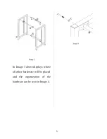
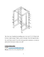
In the Image 1 above the arrows
display where the bottom and top
crossbeam will be attached with
parts L and I. The organization of
the hardware for these locations
can be seen in Image 2.
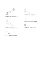
Part B will have part H placed
with it in the organization
displayed above in Image 2 and
part D will have part H placed
with it in the same organization
as part B.
4

