background image

2.5 x 2.5 Power Rack with Belt Squat

Содержание 2.5 x 2.5 Power Rack with Belt Squat

Страница 1: ...2 5 x 2 5 Power Rack with Belt Squat...

Страница 2: ...s alcohol or medication A moment of inattention while operating or assembling the strength equipment may result in serious or fatal injury EQUIPMENT USE AND CARE Visually inspect all components in ord...

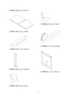
Страница 3: ...ed Tools Crescent Wrench 9 16 Socket and Wrench 5 32 Allen Key Parts 2 5PRBS 001 x1 Part A OR 2 5PR 100 x1 Part MB Upgrade Replaces Part A 2 5PRBS 002 x1 Part B 2 5PRBS 003 x1 Part C 2 5PRBS 004 x2 Pa...

Страница 4: ...2 5PRBS 005 x1 Part E 2 5PRBS 006 x1 Part F 2 5PRBS 007 x2 Part G 2 5PRBS 008 x1 Part H 2 5PRBS 009 x1 Part I 2 5PRBS 010 x1 Part J 2 5PRBS 011 x1 Part K 2 5PRBS 012 x1 Part L 3...

Страница 5: ...2 5PRBS 013 x2 Part M 76 Cable x1 Part N 84 Cable x1 Part O 2 5PRBS 016 x2 Part R 2 5PRBS 017 x2 Part S 2 5PRBS 018 x10 Part T 2 5PRBS 014 x2 Part P 4...

Страница 6: ...Q Carabiner x3 Part V Flat Washer x32 Part W Lock Nut x40 Part X Wing Nut x2 Part AB x 7 5 Bolt x2 Part Y Rubber Stopper x2 Part Z Spacer x2 Part AC Set Screw Collar x2 Part AD x 4 Bolt x40 Part AA P...

Страница 7: ...Assembly Image 1 above displays the assembly of the L M Z and AD 6...

Страница 8: ...h parts R and O respectively The organization of the hardware for these locations can be seen in Image 3 below Part C will have part R placed with it in the organization displayed in Image 3 above and...

Страница 9: ...Image 4 above displays where parts A B and C will be attached and the organization of the hardware can be seen in Image 5 8...

Страница 10: ...Using the parts that were assembled in image 1 place them into part E until the assembly is above part C and slide them into part C Once inserted tighten part part AD with a 5 32 allen key 9...

Страница 11: ...arts Y H G AB and AE will come pre assembled in the manner displayed above Parts H and AE can be placed in different locations as desired above simply shows them placed in the center holes of part G 1...

Страница 12: ...as seen in image 8 above The assembly created in image 7 will be placed beneath the parts I and J as seen in image 8 Parts I J and the previous assembly will be attached with parts AA and X Part AC wi...

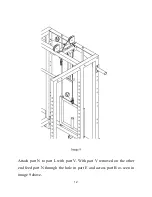
Страница 13: ...Attach part N to part L with part V With part V removed on the other end feed part N through the hole in part E and across part B as seen in image 9 above 12...

Страница 14: ...Image 10 above displays the organization of the remaining hardware which will be used for part T 13...

Страница 15: ...Place P R and S in desired location 14...

Страница 16: ...ace part F on top of part D Attach part O to N with part V Feed part O underneath part F ensuring that it lines up with the pulley underneath part F These parts can be removed and attached as desired...

Страница 17: ...To use the low cable system attach part O to N with V and feed it through part K as seen in image 13 These parts can be removed and attached as desired 16...

Страница 18: ...and Belt Squat Attachment Thank you for choosing Texas Strength Systems for your fitness needs If you have any questions comments or concerns please don t hesitate to contact our staff Contact Inform...

Отзывы: