background image


29 


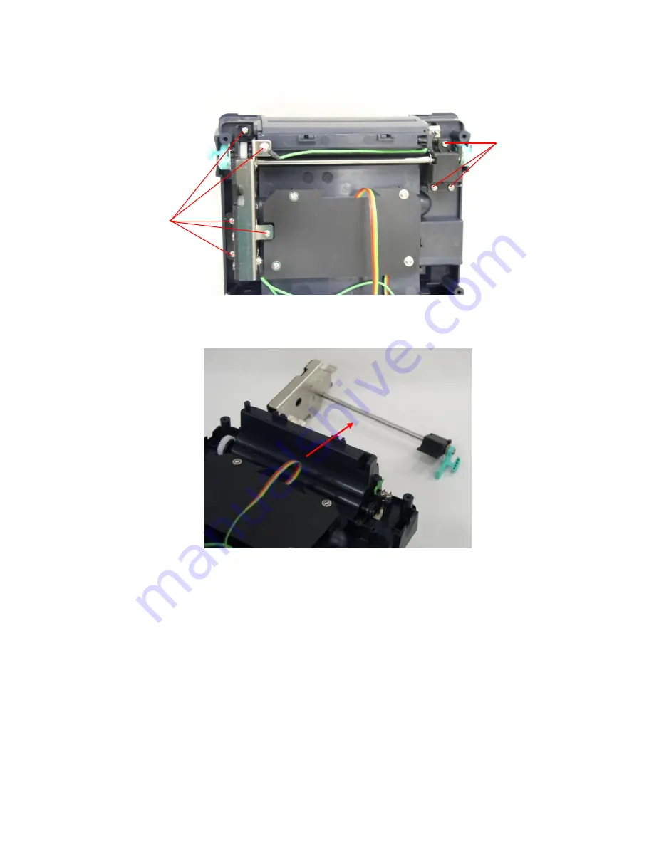
7.  Remove the 

stepping motor bracket / metal ass

’y.


8.  Reassemble parts in reverse procedures. 

Screws 

Screws 

Содержание TTP-245 Plus

Страница 1: ...SERVICE MANUAL TTP 247 TTP 345 TTP 245 Plus TTP 343 Plus THERMAL TRANSFER DIRECT THERMAL BAR CODE PRINTER ...

Страница 2: ...4 Replacing Main Board 26 3 5 Replacing Platen Assembly 27 3 6 Replacing the Stepping Motor Bracket Metal Assembly and Stepping Motor 28 3 7 Replacing Label Guide Gap Sensor Assembly 30 3 8 Replacing Black Mark Sensor Assembly 32 3 9 Replacing Print Head Assembly 33 3 10 Replacing Head Open Micro Switch 34 3 11 Replacing Ribbon Motor and Ribbon Sensor 36 3 12 Replacing Feed Button and Feed Button ...

Страница 3: ...zation 56 4 4 Black Mark Sensor Calibration 57 4 5 Gap Sensor Calibration 57 4 6 Skip AUTO BAS 57 5 GAP AND BLACK MARK SENSOR SELECTION 59 6 BIOS Update 59 7 DIAGNOSTIC TOOL 60 7 1 Start the Diagnostic Tool 60 7 2 Printer Function Calibrate sensor Ethernet setup RTC setup 61 8 TROUBLESHOOTING 62 9 MAINTENANCE 66 UPDATE HISTORY 68 ...

Страница 4: ...1 1 FUNDAMENTAL OF THE SYSTEM 1 1 Overview 1 1 1 Front View Fig 1 1 1 Front View Top Cover Open Lever Ribbon Access Window Feed Button LED Indicator Label Roll Capacity View Window ...

Страница 5: ...2 1 1 2 Rear View Fig 1 1 2 Rear View 1 USB Interface 2 Centronics Interface 3 RS 232 Interface 4 Power Jack 5 Power Switch 6 Rear Paper Guide 1 2 3 4 5 6 ...

Страница 6: ... dimension 314mm L x 213mm W x 188mm H Ribbon capacity 300 meter 1 core Label roll capacity 5 OD Processor 32 bit RISC high performance processor Memory 2MB Flash memory 8MB DRAM SD card slot for memory expansion Interface RS 232 max 115200 bps Centronics USB 2 0 Full speed mode Power External universal switching power supply Input AC 100 240V Output DC 24V 3 75A Operation switch button One power ...

Страница 7: ...page 1254 Turkish Codepage 1257 Baltic Codepage 1258 Vietnam ISO 8859 1 Latin 1 Western European ISO 8859 2 Latin 2 Central European ISO 8859 3 Latin 3 South European ISO 8859 4 Latin 4 North European ISO 8859 5 Cyrillic ISO 8859 7 Greek ISO 8859 9 Turkish ISO 8859 10 Nordic ISO 8859 15 Latin9 Bar code 1D bar code Code 39 Code 93 Code128UCC Code128 subset A B C Codabar Interleave 2 of 5 EAN 8 EAN ...

Страница 8: ...m 0 31 Printout bias Vertical 1 mm max Horizontal 1 mm max Environment condition Operation 5 40 o C 25 85 non condensing Storage 40 60o C 10 90 non condensing Safety regulation FCC Class B CE Class B C Tick Class B UL CUL TÜ V GS CCC Accessories BarTender UltraLite CD disk Quick start guide USB cable External universal switching power supply Power Cord Label Spindle fixing tab x2 1 5 core adapter ...

Страница 9: ...rver External roll mount media OD 214 mm 8 4 with 3 core label spindle Contact CCD contact scanner Long range linear image bar code scanner 1 2 2 Printer TTP 247 TTP 345 Item Printer model TTP 247 TTP 345 Resolution 203 DPI 300 DPI Printing method Thermal Transfer Direct Thermal Print speed 2 3 4 5 6 7 ips 2 3 ips for peeler mode 2 3 4 5 ips 2 ips for peeler mode Max print width 108 mm 4 25 106 mm...

Страница 10: ...power supply Input AC 100 240V Output DC 24V 3 75A Operation switch button One power switch One feed button One LED 3 colors green amber red Sensors Gap transmissive sensor offset 6 mm from liner edge Black mark reflective sensor position adjustable Head open Ribbon end sensor Internal font 8 alpha numeric bitmap fonts One Monotype Imaging CG Triumvirate Bold Condensed scalable font Build in Monot...

Страница 11: ...57 Baltic Codepage 1258 Vietnam ISO 8859 1 Latin 1 Western European ISO 8859 2 Latin 2 Central European ISO 8859 3 Latin 3 South European ISO 8859 4 Latin 4 North European ISO 8859 5 Cyrillic ISO 8859 7 Greek ISO 8859 9 Turkish ISO 8859 10 Nordic ISO 8859 15 Latin9 Bar code 1D bar code Code 39 Code 93 Code128UCC Code128 subsets A B C Codabar Interleave 2 of 5 EAN 8 EAN 13 EAN 128 UPC A UPC E EAN a...

Страница 12: ... Horizontal 1 mm max Environment condition Operation 5 40 o C 41 140 o F 25 85 non condensing Storage 40 60o C 40 140o F 10 90 non condensing Safety regulation FCC Class B CE Class B C Tick Class B UL CUL TÜ V Safety CCC Accessories Windows labeling software CD disk Quick start guide USB cable External universal switching power supply Power Cord Label Spindle fixing tab x2 1 5 core adapter x2 Ribb...

Страница 13: ... power is on and the device is ready to use Green Flash This illuminates that the system is downloading data from PC to memory and the printer is paused Amber This illuminates that the system is clearing data from printer Red Solid This illuminates printer head open cutter error Red Flash This illuminates a printing error such as paper empty paper jam ribbon empty or memory error etc 1 2 4 Button ...

Страница 14: ...t GAP and BLINE command please refer to TSPL2 programming manual Gap Black Mark Sensor Calibratio Label Length Measurement Self Test and enter Dump Mode 1 Turn off the power switch 2 Hold on the button then turn on the power switch 3 Release the button when LED becomes amber and blinking Any amber will do during the 5 blinks The LED color will be changed as following order Amber red 5 blinks amber...

Страница 15: ...er switch 2 Hold on the button then turn on the power switch 3 Release the button when LED turns green amber after 5 green blinks Any green amber will do during the 5 blinks The LED color will be changed as following Amber red 5 blinks amber 5 blinks green 5 blinks green amber 5 blinks red amber 5 blinks solid green Force Gap Sensor Calibration 1 Turn off the power switch 2 Hold on the button then...

Страница 16: ...en turn on power 3 Release the FEED button when LED becomes solid green The LED color will be changed as following Amber red 5 blinks amber 5 blinks green 5 blinks green amber 5 blinks red amber 5 blinks solid green 4 Printer will be interrupted to run the AUTO BAS program ...

Страница 17: ... cutter 10mm 1000mm 0 4 39 25 4mm 1000mm 1 39 Thickness 0 06mm 0 19mm Roll Diameter 5 Roll Core Diameter 25 4mm 76 2mm 1 3 Gap Height 2mm min Black Mark Height 2mm min Black Mark Width 8mm min 1 3 2 Ribbon Item Specification Type Wax Wax Resin Resin Core Diameter 1 Width Max 110mm Capacity 300m with 1 core Wound Type Outside wound Ribbon End Clear or silver end tape ...

Страница 18: ...oard Connectors Main board Top Connector Description Remark 1 Centronics port connector JP4 2 USB connector JP9 3 RS 232C connector JP7 4 Micro processor U2 5 RFID module connector JP36 1 2 3 4 5 6 7 7 7 8 9 10 11 12 14 13 15 16 17 18 ...

Страница 19: ... AD 0 3 3V 3 Power 3 3V 4 Gap sensor emitter 2 5 3 0V 5 Gap sensor power 3 0 3 3V JP41 Pin Description Voltage 1 Gap sensor power 3 0 3 3V 2 Black mark sensor power 3 0 3 3V 3 Black mark sensor emitter 2 5 3 0V 4 Black mark sensor receiver AD 0 3 3V 5 Power 3 3V 8 Ribbon sensor connector JP18 Pin Description Voltage 1 Ribbon sensor emitter On 3 7 3 9V Off 4 3 4 6V 2 Power 5V 3 Ribbon sensor receiv...

Страница 20: ...l sensor receiver AD 0 3 3V 3 Peel sensor emitter Emitter on 1 0 1 2V Emitter off 0V 4 Power 5V 5 Reserved 12 Power supply output 24V DC connector B3 13 Power switch SW2 14 Print head connector JP42 15 Stepping motor connector JP14 16 Ethernet connector Factory option JP43 17 LED connector JP28 Pin Description Voltage 1 Power 3 3V 2 LED green LED light on 1 1 1 4V LED light off 1 6 1 9V 3 LED red ...

Страница 21: ...18 Main board Bottom Connector Description Remark 1 Cutter driver IC connector U30 2 SD card slot JP2 3 RTC battery Factory option BT2 1 2 3 ...

Страница 22: ...host When this pin is de asserted the ve clock edge should be used to shift the data into the device 2 9 Data 0 7 N A In Data Bus Single directional 10 Ack N A Out A low on this line indicates that there are valid data at the Device When this pin is de asserted the ve clock edge should be used to shift the data into the host 11 Busy N A Out When in reverse direction a high indicates data while a l...

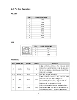
Страница 23: ... No Defined N A N A 16 17 Ground N A GND Ground 18 No Defined N A N A 19 30 Ground N A GND Ground 31 No Defined N A N A 32 Error Fault N A Out A low set by the device indicates that the reverse data is available 33 35 Ground N A GND Ground 36 No Defined N A N A Ethernet PIN CONFIGURATION 1 Tx 2 Tx 3 Rx 4 N C 5 N C 6 Rx 7 N C 8 N C ...

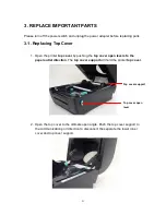
Страница 24: ...ter top cover by pushing the top cover open levers to the paper outlet direction The top cover support will hold the printer top cover 2 Open the top cover to the ultimate open angle Push the top cover support to the communication port direction to disconnect the separate the lower inner cover and top cover support Top cover support Top cover open lever ...

Страница 25: ...22 3 Remove the 6 screws in the top inner cover 4 Disconnect the harness from the Feed button PCB Replace the top cover 5 Reassemble parts in reverse procedures Screws Screws ...

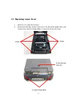
Страница 26: ...er upside down and remove the 2 screws of hinge holder 1 screw of memory card cover 3 Disconnect all the harnesses from Main Board Lift up the lower inner cover Turn the lower inner cover upside down and remove the 6 screws of lower inner cover and hinge holders 2 screws of hinge holder Screw of memory card cover Screws Screws ...

Страница 27: ...24 4 Replace the top inner cover 5 Reassemble in reverse procedures ...

Страница 28: ...r to 3 1 to open the top cover 2 Remove the 6 screws of lower inner cover Turn the printer upside down and remove the 2 screws of hinge holder 1 screw of memory card cover Screws Screws 2 screws of hinge holder Screw of memory card cover ...

Страница 29: ...n reverse procedures 3 4 Replacing Main Board 1 Please refer to 3 3 for disassembling the LOWER COVER and LOWER inner cover 2 Disconnect all harnesses 3 Remove 4 screws on the main board 4 Replace the main board lower inner cover 5 Reassemble parts in reverse procedures Screw Screw Screw Screw Lower Cover Main Board ...

Страница 30: ...27 3 5 Replacing Platen Assembly 1 Squeeze two sides of platen assembly and take it out 2 Replace a platen 3 Reassemble it in reverse procedures Squeeze Here Platen Squeeze Here ...

Страница 31: ...ling the lower cover and lower inner cover 2 Disconnect all hardness 3 Turn the lower inner cover upside down 4 Remove 2 screws that fixed the stepping motor on the bracket 5 Remove the stepping motor 6 Use a screwdriver to screw off 8 screws of the stepping motor bracket metal ass y Screws Motor Lower inner cover ...

Страница 32: ...29 7 Remove the stepping motor bracket metal ass y 8 Reassemble parts in reverse procedures Screws Screws ...

Страница 33: ...and remove the plastic laminate 5 Screws off 2 screws to remove the white label guide rack fixing plate 6 Remove 2 screws from a gap sensor PCB then remove the gap sensor PCB 7 Turn over the lower inner cover 8 Move right side and left side label guides to the end of each side Rotates 90 degrees and pull them out Screws Screws Label Guide Rack Fixing Plate Screw Gap Sensor PCB Plastic Laminate Low...

Страница 34: ...31 9 Reassemble parts in reverse procedures Label Guide Lower inner cover ...

Страница 35: ...Upside down the lower inner cover Remove 4 screws and remove the plastic laminate 4 Remove 1 screw from the black mark sensor 5 Upside down the lower inner cover 6 Replace the black mark sensor assembly 7 Reassemble parts in reverse procedures Screw Black Mark Sensor Lower inner cover Black Mark Sensor Fixing Plate Lower inner cover Black Mark Sensor ...

Страница 36: ...the print head bracket and use a flat screwdriver to stick left side of the printer head bracket then pick up the print head assembly 2 Disconnect print head harnesses 3 Reassemble parts in reverse procedures Bracket Concave Print Head Stick Flat Screwdriver Here ...

Страница 37: ...h 1 Please refer to 3 1 for disassembling the top cover and top inner cover 2 Disconnect ribbon mechanism by removing 4 screws at top inner cover 3 Remove 2 screws and remove the head open micro switch Mechanism Screws Screws Top inner cover ...

Страница 38: ...35 4 Reassemble parts in reverse procedures Screws Head Open Micro Switch ...

Страница 39: ...2 Disconnect ribbon mechanism by removing 4 screws from the top inner cover 3 Remove 2 screws on the ribbon motor PCB 4 Replace the ribbon motor sensor 5 Screw off 2 screws from the top inner cover 6 Replace the ribbon sensor 7 Reassemble parts in reverse procedures Screws Ribbon Motor Sensor Screws Screws Ribbon Mechanism ...

Страница 40: ...37 Screws Ribbon Sensor Top inner cover ...

Страница 41: ...r disassembling the top cover and top inner cover 2 Turn the top cover upside down 3 Screw off 2 screws on feed button PCB and remove feed button PCB 4 Use a flat head driver to poke up the feed button 5 Reassemble parts in reverse procedures Screws Top Cover Feed Button PCB ...

Страница 42: ...pacity Approved SD card manufacturer V1 0 V1 1 128 MB SanDisk Transcend V1 0 V1 1 256 MB SanDisk Transcend Panasonic V1 0 V1 1 512 MB SanDisk Transcend Panasonic V1 0 V1 1 1 GB SanDisk Transcend Panasonic V2 0 SDHC CLASS 4 4 GB V2 0 SDHC CLASS 6 4 GB SanDisk Transcend Panasonic V1 0 V1 1 microSD 128 MB Transcend Panasonic V1 0 V1 1 microSD 256 MB Transcend Panasonic V1 0 V1 1 microSD 512 MB Panaso...

Страница 43: ...nscend Panasonic V1 0 V1 1 miniSD 512 MB Transcend Panasonic V1 0 V1 1 miniSD 1 GB Transcend Panasonic V2 0 SDHC CLASS 4 miniSD 4 GB Transcend V2 0 SDHC CLASS 6 miniSD 4 GB The DOS FAT file system is supported for the SD card Folders files stored in the SD card should be in the 8 3 filename format The miniSD microSD card to SD card slot adapter is required ...

Страница 44: ...top cover open levers to separate the lower inner cover and the lower cover Please refer to section 3 1 5 Connect the harness of peel off module through the slot of lower inner cover 6 Lift up the lower inner cover to gently push peel off panel into the two concaves of lower cover front side Note Must lift up the lower inner cover first then the peel off module could be installed into the concave ...

Страница 45: ...nect the harness of peel off module at JP19 on the main board 8 Put down the lower inner cover onto lower cover 9 Push peel off module to lock to the lower inner cover 10 Reassemble parts in reverse procedures ...

Страница 46: ...off function 1 Insert a 1 label spindle into a paper roll 2 Open the printer top cover by pushing forward the top cover open levers The top cover support will hold the printer top cover 3 Install the paper roll on the paper roll mount 4 Open the peel off panel by pulling it out Peel off panel Top Cover Open Lever Backing paper Opening Peel off panel ...

Страница 47: ... guide by removing left or right to fit the paper width Lead the paper through the backing paper opening beneath the roller 8 Push the peel off panel back to the printer 9 Close the top cover by lifting up the top cover support and close the top cover slowly Note Pull the label outward tightly after closing the top cover Complete label installation for peel off mode Roller Top Cover Peel off panel...

Страница 48: ...printer to remove two screws of hinge holder in the lower cover 2 Remove the screw that fixes the memory card cover 3 Plug in the Cutter Driver IC at U30 socket on the main board Cutter Driver IC Screw of hinge holder Screw of hinge holder Memory card cover ...

Страница 49: ...ection The top cover support will hold the printer top cover 5 Open the top cover to the ultimate open angle Push the top cover support to the communication port direction to disconnect the lower inner cover and top cover support 6 Pull up the front panel from the lower cover Top cover support ...

Страница 50: ...over from the Lower Cover 9 Install the 4 pin connector of the cutter onto JP38 on the main board Pull the wire of the 4 pin connector through the slot of lower inner cover front side Then put back the lower inner cover Location JP38 Screws Screws Wire of the 4 pin connector ...

Страница 51: ...er module into the two slots of lower inner cover front side then push cutter to lock into the lower inner cover 11 Assemble the memory card cover 12 Reassemble parts in reverse procedures Cutter wire Slot Lower inner cover ...

Страница 52: ...through the paper guide and pass over the platen 5 Lead the paper through the cutter paper opening 6 Adjust the paper guide by removing left or right to fit the paper width Label installation in cutter mode 7 Close the top cover by lifting up the top cover support and close the top cover slowly Complete label installation in cutter mode Top Cover Paper Guide Platen Cutter Top Cover Support ...

Страница 53: ...ing 2 Remove the screw from the main board Fasten the copper pillar 3 Plug the RJ45 cable connector to the RJ45 daughter board connector Fasten the RJ45 connector daughter board upon the lower cover and copper pillar The ground wire from the mechanism must be screwed on the daughter board at copper pillar RJ45 interface opening Remove the screw Copper pillar ...

Страница 54: ... main board JP43 connector Note This internal Ethernet interface only supports with the main board that has print server function on board Screws Ground wire RJ45 8 PIN connector interface cable interface cable RJ45 connect daughter board ...

Страница 55: ...ed at the following conditions 1 A brand new printer 2 Change label stock 3 Printer initialization Please follow the steps below to calibrate the ribbon and gap black sensor 1 Turn off the power switch 2 Hold on the button then turn on the power switch 3 Release the button when LED becomes red and blinking Any red will do during the 5 blinks It will calibrate the ribbon sensor and gap black mark s...

Страница 56: ...on then turn on the power switch 3 Release the button when LED becomes amber and blinking Any amber will do during the 5 blinks The LED color will be changed as following order Amber red 5 blinks amber 5 blinks green 5 blinks green amber 5 blinks red amber 5 blinks solid green 1 It calibrates the sensor and measures the label length and prints internal settings then enter the dump mode Note Please...

Страница 57: ...leage meter Firmware checksum Serial port configuration Code page Country code Print speed inch sec Print darkness Label size inch Gap distance inch Gap black mark sensor sensitivity Numbers of download files Total available memory space Note 1 The physical flash memory for RoHS compliant version is 2MB Flash and 8MB SDRAM 2 System occupies 960 KB in Flash memory so total flash memory space for us...

Страница 58: ...ng The left side characters are received from your system and right side data are the corresponding hexadecimal value of the characters It allows users or engineers to verify and debug the program Fig 4 Dump mode printout Note Turn off on the power to resume printer for normal printing ASCII Data Hex decimal data related to left column of ASCII data ...

Страница 59: ...Amber red 5 blinks amber 5 blinks green 5 blinks green amber 5 blinks red amber 5 blinks solid green Printer configuration will be restore to defaults as below after initialization Parameter Default setting Speed 203 dpi 127 mm sec 5 ips 300 dpi 76 mm sec 3 ips Density 8 Label Width 4 101 6 mm Label Height 4 101 6 mm Sensor Type Gap sensor Gap Setting 0 12 3 0 mm Print Direction 0 Reference Point ...

Страница 60: ...urn off the power switch 2 Hold on the button then turn on the power switch 3 Release the button when LED turns red amber after 5 green amber blinks Any red amber will do during the 5 blinks The LED color will be changed as following Amber red 5 blinks amber 5 blinks green 5 blinks green amber 5 blinks red amber 5 blinks solid green 4 6 Skip AUTO BAS TSPL2 programming language allows user to downl...

Страница 61: ...8 The LED color will be changed as following Amber red 5 blinks amber 5 blinks green 5 blinks green amber 5 blinks red amber 5 blinks solid green 2 Printer will be interrupted to run the AUTO BAS program ...

Страница 62: ...switch sensor from gap to black mark sensor Remember always do sensor calibration after sensor selection refer to Gap and Black Mark Sensor Calibration section 6 BIOS Update If printer BIOS update is required please do the following steps Update the BIOS file and reset the printer Update File 1 Make sure the printer is at ready status and the LED is solid green 2 Copy the BIOS file to printer para...

Страница 63: ... this convenient tool you can explore the printer status and settings and troubleshoot the printer Note This utility works with printer firmware V6 00 and later versions 7 1 Start the Diagnostic Tool 1 Double click on the Diagnostic tool icon to start the software 2 There are four features Printer Configuration File Manager Bitmap Font Manager Command Tool included in the Diagnostic utility Featur...

Страница 64: ...t Setup Setup the IP address subnet mask gateway for the on board Ethernet RTC Time Synchronize printer Real Time Clock with PC Print Test Page Print a test page Reset Printer Reboot printer Factory Default Initialize the printer and restore the settings to factory default Dump Text To activate the printer dump mode Ignore AUTO BAS Ignore the downloaded AUTO BAS program Configuration Page Print pr...

Страница 65: ... use diagnostic tool to get the printer status through COM port or USB port Label runs out Out of paper Load a roll of label and follow the instructions as following and then press the feed button to resume printing 1 Insert a 1 label spindle into a paper roll 2 Open the printer s top cover by releasing the green top cover open levers located on each side of the printer and lifting the top cover A...

Страница 66: ...ower The printer will be switched to thermal direct mode automatically If the printer LED is still on red blink please check the following A Is a paper core installed on the ribbon rewind spindle B Is ribbon installed correct along the ribbon path C Is the ribbon too transparent D Is the rib of the ribbon spindle is broken E Is the ribbon gear broken or worn F Turn off printer power Rewind the rib...

Страница 67: ...lization to reset the system 6 Continuous feeding labels The printer setting may go wrong Please do Printer Initialization and Gap and Black Mark Sensor Calibration Refer to 4 2 and 4 3 7 No print on the label Is the label or ribbon loaded correctly Refer to No 3 Label runs out and Ribbon runs out to load the paper or to load the ribbon Does the ribbon run out Is the thermal head connector connect...

Страница 68: ...ard are broken 11 LED keeps at solid amber Is switching power broken Is main board broken Please replace a new main board Try to update the firmware on line Press the FEED and power on the printer at same time Press the FEED again while the first green LED is on Finally transmit the firmware program to the printer from PC 12 Cutter functions abnormally Cutter is not activated other error At first ...

Страница 69: ...int head 2 Allow the print head to cool for a minimum of one minute 3 Use a cotton swab Head cleaner pen and 100 ethanol to clean the print head surface Clean the print head when changing a new label roll Platen Roller 1 Turn the power off 2 Rotate the platen roller and wipe it thoroughly with 100 ethanol and a cotton swab or lint free cloth Clean the platen roller when changing a new label roll T...

Страница 70: ... hand If you touch it careless please use ethanol to clean it Please use 100 Ethenol DO NOT use medical alcohol which may damage the printer head Regularly clean the print head and supply sensors once change a new ribbon to keep printer performance and extend printer life ...

Страница 71: ...2008 6 16 1 Revise the hinge holder part no 2 Revise the TPH plastic bracket part no Camille 2008 7 11 Remove the parts list section Camille 2008 12 12 Add connector JP6 description Camille 2009 3 16 Modify section 3 13 Recommended SD card specification Camille 2009 10 6 Revise section 2 1 Camille 2010 7 1 Add TTP 247 TTP 345 printer Add the section 1 2 2 Update the section 7 Camille 2011 1 17 Mod...

Страница 72: ...st Rd Wujie Township New Taipei City 23141 Taiwan R O C Yilan County 26841 Taiwan R O C TEL 886 2 2218 6789 TEL 886 3 990 6677 FAX 886 2 2218 5678 FAX 886 3 990 5577 Web site www tscprinters com E mail printer_sales tscprinters com tech_support tscprinters com TSC Auto ID Technology Co Ltd ...

Отзывы: