31
TTP-243 Plus/ 243E Plus/
342 Plus Bar Code Printer
4. MECHANISM
4.1 Cutter Installation
1. Turn off the printer power.
2. Open the top cover of the printer.
3. Remove the printer front panel slowly and carefully. (Cf. Fig. 3.14)
4. Remove the two screws and the metal cover. (Cf. Fig. 3.15)
5. Release the cable tie and remove the peel-off sensor connector. (Cf. Fig. 3.16)
6. Remove the peel-off sensor connector.
7. Plug in the cutter connector.
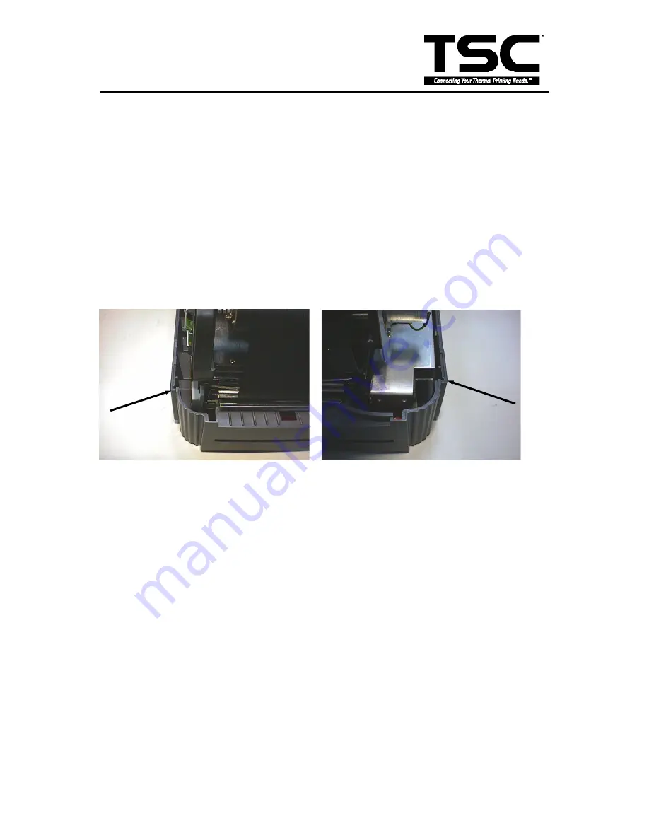
8. Insert the right and left side flange of cutter into the slot.
Fig. 4.1 Cutter Installation
9. Fasten the cutter from the bottom of the printer with the provided screw.
10. Make sure no screws or other parts are left in the printer.
11. Reassemble the mechanism and internal label roll mount in the reverse procedures of the
removal.
Right Flange
Left Flange


