background image

............ www.truemfg.com ............

True Food Service Equipment, Inc.

12

12

INSTALLATION / OPERATION INSTRUCTIONS

DEFROST TIME CLOCK OPERATION

Instructions for TAC-48, TAC-48GS, and TAC-72RC models.

RECOMMENDED DEFROST 
SETTINGS:

TRUE Manufacturing has factory 

set your defrost time clock to a 

recommended time and duration defrost 

scenario. Your TRUE equipment has 

been designed for three defrost periods 

(6:00 a.m., 2:00 p.m. and 10:00 p.m.). If 

you decide to deviate from these defrost 

time settings please follow the procedures 

for adjustment below.

NOTE:

Defrost timer will need to be set at current 

time of day before plugging unit into power 

supply. The defrost times have been set 

from the factory. If you want to change 

defrost times please read through the 

defrost timer instructions.

REQUIRED TOOLS:

• Phillips Screwdriver

• 1/4” Nut Driver or Socket

TAC Defrost Timer Location:

Defrost timer is located in a ballast box 

behind the front louvered grill on the left 

side of the unit. Four corner screws on 

the front louvered grill will need to be 

removed. The ballast box has two 1/4” 

hex head screws that need to be removed 

to gain access to the defrost control.

Setting the timer:
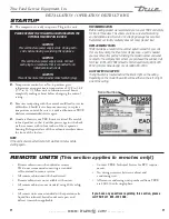
(UNPLUG UNIT FROM 
POWER SUPPLY!) 

DO NOT SET THE TIME BY 
ROTATING THE “OUTER” DIAL.

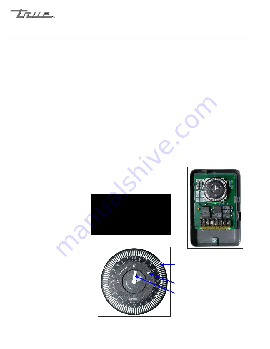
Turn the minute hand clockwise until the 

time of day on the outer dial is aligned 

with the triangle marker on the inner dial 

(two o’clock position). 

Adjusting The Defrost Timer:

(time initiated, time terminated)

Your TRUE equipment contains a defrost 

system that is time initiated and time 

terminated. While TRUE requires a 

minimum 3 defrost periods not to exceed 

30 minutes the procedure on this page 

should be followed to customize your 

specific needs. 

Notice

If timer is not set for a minimum of 3 

defrost per day for 30 minutes each, the 

coil may develop excessive frost. This may 

lead to system failure and product loss, 

which is not covered under warranty. 

The following procedure may be followed 

to customize your needs.

High usage, high temperature, and high 

humidity may require 4 defrost settings 

per day.

WARNING

Always follow the 

manufacturer’s recommended settings 

when programming the amount and 

duration of the 

defrost cycles.

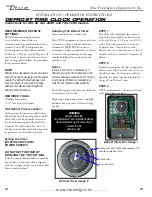
Defrost Timer Image 2

STEP 1

The white tabs located on the outmost 

area of the time clock have been factory 

set for (6:00 a.m., 2:00 p.m., and 10:00 

p.m.). Each tab represents 15 minutes 

of defrost time. Notice that at each 

defrost time two white tabs are set for 15 

minutes each for a total of 30 minutes of 

defrost. 

STEP 2

In order to program the time to begin the 

defrost cycle, flip the white tabs out to set 

the defrost time. To eliminate a defrost 

time flip the white tabs back toward the 

center of the Defrost Timer. 

STEP 3

TRUE recommends a 30 minute defrost 

cycle three times per day. 

Defrost Timer Box Image 1

Outer most dial. White tabs represent 15 
minutes of defrost time.

Time of day.

Inner most dial.

Содержание TAC-30

Страница 1: ...necting Electricity 4 Adapter Plugs 4 Installation Operation Instructions Ownership 5 Required Tools 5 Uncrating 5 Locating 6 Installation of Leg Castors 7 Electrical Instructions 7 Leveling Cabinet 7...

Страница 2: ...www truemfg com True Food Service Equipment Inc...

Страница 3: ...www truemfg com True Food Service Equipment Inc 1 1...

Страница 4: ...sonnel Do not puncture refrigerant tubing Caution Risk of fire or explosion Flammable refrigerant used Consult repair manual owner s guide before attempting to service this product All safety precauti...

Страница 5: ...s in place so that children may not easily climb inside Refrigerant Disposal Your old refrigerator may have a cooling system that uses Ozone Depleting chemicals If you are throwing away your old refri...

Страница 6: ...cks or abrasion damage along its length or at either end When removing the freezer away from the wall be careful not to roll over or damage the power cord HOW TO CONNECT ELECTRICITY Do not under any c...

Страница 7: ...crating the unit A Remove the outer packaging by pulling tri wall nails from skid Remove 4 cardboard corner pads and dust cover B Inspect for concealed damage Again immediately file a claim with the f...

Страница 8: ...lace screws B Skid bolts are located in each of 4 corners inside cabinet bottom see image 4 C Remove skid bolts see image 5 D Cut straps if applicable see image 6 E Carefully lift cabinet off of skid...

Страница 9: ...ompressor warranties are void if compressor burns out due to low voltage WARNING Power supply cord ground should not be removed WARNING Do not use electrical appliances inside the food storage compart...

Страница 10: ...8 6 6 6 6 5 4 4 3 35 10 10 8 6 6 6 5 5 4 4 3 2 40 10 8 8 6 6 5 5 4 4 3 2 2 45 10 8 6 6 6 5 4 4 3 3 2 1 50 10 8 6 6 5 4 4 3 3 2 1 1 Wire Gauge for 2 Voltage Drop in Supply Circuits 230 Volt Distance In...

Страница 11: ...end you run your TRUE unit empty for two to three days This allows you to be sure electrical wiring and installation are correct and no shipping damage has occurred Remember our factory warranty does...

Страница 12: ...rts on either side of cabinet come out by backing out three hex screws 1 4 on each side Larger units will have a center shelf support that will need to be removed STEP 4 Once shelf supports are remove...

Страница 13: ...able results further adjustment is possible in the field Disconnect power to the cabinet Remove the full length back panel that the temperature control is mounted to See figure 1 2 The temperature pro...

Страница 14: ...rker on the inner dial two o clock position Adjusting The Defrost Timer time initiated time terminated Your TRUE equipment contains a defrost system that is time initiated and time terminated While TR...

Страница 15: ...d HOW TO RESET THE MAXIMUM AND MINIMUM TEMPERATURE RECORDED To reset the stored temperature when maximum or minimum temperature is displayed 1 Press SET key until rST label starts blinking HOW TO SEE...

Страница 16: ...www truemfg com True Food Service Equipment Inc 14 14 DIGITAL TEMPERATURE CONTROLLER PROGRAMMING INSTRUCTIONS CONTINUED...

Страница 17: ...U S Commercial homepage under Support tab 3 Contact our service department at US 1 855 372 1368 UK 44 0 1709 888080 Mexico 52 555 804 6343 44 email service truemfg com We want to make it very clear th...

Страница 18: ...temperature that will start the compressor Example If the Set Point is 9 F 23 C and the Differential is 10 F 5 C Set Point 9 F 10 Differential 1 F Or Set Point 23 C 5 Differential 18 C The compressor...

Страница 19: ...lock settings If no appears the controller is unlocked If yes appears the controller is locked See images 3 and 4 C Once the lock setting has been set correctly release the info button Wait 5 seconds...

Страница 20: ...n B To control interior sign lights by the interior door switch depress the rocker switch to the ON position Light Switch is located on inside top right or top left of the ceiling ON Position May need...

Страница 21: ...ntrol Icons May need to unlock control WHY THE SET POINT IS THE TEMPERATURE AT WHICH THE COMPRESSOR WILL SHUT OFF Please note that the set point IS NOT the cabinet holding temperature HOW A To see the...

Страница 22: ...roller is preprogrammed for TIM press and release the Manual Defrost button until dEF appears B REAL TIME CLOCK RTC If controller is preprogrammed for RTC press the and hold the Manual Defrost button...

Страница 23: ...he set point press and hold the info button and the stand by button at the same time ScL will appear See image 1 B Push the up button until dFt appears See image 2 C Press and hold the info button to...

Страница 24: ...www truemfg com True Food Service Equipment Inc 22 22 LAE DISPLAY...

Страница 25: ...228 DDY OS2 X 1 8 75 167 1 925 FID T3 80 176 1 669 FDD X 32 1 8 OS3 X 1 8 85 185 1 452 FTO TLD 90 194 1 268 FCM SIM 95 203 1 145 FDT X 1 8 ADR 100 212 0 974 FDH X 1 8 105 221 0 858 FT1 110 230 0 758...

Страница 26: ...junction box shown in this picture This cabinet is rated for 115 volt 15 amp circuit Supply wiring connections should meet local electrical codes INSTALLING REMOTE UNITS A Refrigeration Line Connecti...

Страница 27: ...he floor for flat shelves Wire shelves are oriented so that cross support bars are facing down C Place shelves on shelf clips making sure all corners are seated properly NOTE Do not load product to wh...

Страница 28: ...TRIP INSTALLATION A Take the shelf and turn it around The back of the shelf should be facing out See image 1 2 B The flavor strip snaps onto the shelf with the larger opening of the strip toward the b...

Страница 29: ...op of louver TAC 14GS Grill Removal Remove two screws from either side of the front grill See image 1 Lift grill away front cabinet See image 2 Step 3 Clean off accumulated dirt from condensing coil w...

Страница 30: ...e a group of vertical fins You need to be able to see through the condenser for the unit to function at maximum capacity Do not place filter material in front of condensing coil This material blocks a...

Страница 31: ...oft cloth when you cannot see the grain 3 Use alkaline alkaline chlorinated or non chloride containing cleaners While many traditional cleaners are loaded with chlorides the industry is providing an e...

Страница 32: ...rgent can be applied with a sponge or cloth to remove grease and oil F Benefit Super Sheen Sheila Shine are good for restoration passivation NOTE The use of stainless steel cleaners or other such solv...

Страница 33: ...ms must be achieved to insure low moisture levels in the system 500 microns or lower must be obtained All claims for labor or parts must be made directly through TRUE All claims should include model n...

Отзывы: