background image

10

EQUIPMENT MAINTENANCE

TRANSMISSION MAINTENANCE

The transmission was lubricated at the
factory and should not require any further
lubrication.
However, you should check the lubricant
level after the first five (5) hours of opera-
tion and every twenty-five (25) operating
hours thereafter.  If needed, use a high-
quality, automotive-grade petroleum-
based grease.

To check the transmission:

1. Stop the engine, let it cool and discon-
nect the spark plug wire.

2. Place the machine down on its left side
so the right end of the tine shaft faces up.

3. Remove the right-side tines (see Tine
Removal and Installation 
in this Section).

4. Clean the transmission housing.

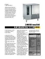
5. Remove the three threaded plugs (A, B
and C, Figure 11) from the transmission. 

Lubricant should be visible in the top two
holes (B and C).  If so, replace all three
plugs. If lubricant is needed, proceed as
follows. 

To lubricate the transmission:

1. Place the nozzle (D, Figure 11) of a
standard grease gun firmly against the
rim of the middle hole (B) and add grease
until it begins to seep from the bottom
hole (A).  Reinstall the plug in the bottom
hole (A).  Next apply grease to the top fill
hole (C) until it begins to seep from the
middle hole (B).  Reinstall the plugs in the
middle (B) and top (C) holes.

2. Before reinstalling the tines, use a fine
grade sandpaper to clean any rust off the
tine shaft.  Apply a few drops of oil to the
tine shaft to make future tine removal
easier.

OTHER LUBRICATION POINTS

• Handlebar Adjustment Knobs:  Spray

occasionally with a silicone type lubri-
cant.

• Throttle/Tines Control Lever Cable:

Squeeze the lever closed and spray a lu-
bricant into the cable area.

• Tine Shaft:  After each use, remove the

tines, clean the tine shaft with sandpaper
and apply a light coat of oil to the tine
shaft. 

HARDWARE/WIRING CONNECTIONS

Before each use, check that all hardware
is tight and that the On/Off Switch wire
connections are secure.  Also check that
the switch wiring is in good condition.

Figure 11: Transmission lubricant check and
fill locations. 

A

D

B

C

Before tipping engine or equipment to
service transmission, drain fuel from
tank by running engine until fuel tank is 
empty.  Allow engine to cool.

WARNING

Before inspecting, cleaning or servicing
the machine, shut off engine, let all
moving parts come to a complete stop,
disconnect the spark plug wire and move
the wire away from the spark plug.
Failure to follow these instructions can
result in personal injury or property
damage.

WARNING

Maintenance

5

Section

REQUIRED MAINTENANCE SCHEDULE

REQUIRED MAINTENANCE

Before 

First

Every 3 

Every 6

Yearly

Every

Perform at every indicated month or 

Each

month

months

months 

2 years

operating hour interval, whichever 

Use

or 10 Hrs. or 25 Hrs. or 50 Hrs.

comes first.  *See Engine Owner’s Manual 
for engine related maintenance.

Check Tightness of Bolts and Nuts 

x

Check Transmission Lubricant Level 

(1) 

x

Clean Machine

x

Clean Tine Shaft

x

Engine Oil Level

Check

x

Change

x

x

Air Cleaner

Check

x

Change

(2)

Spark Plug

Check/Clean

x

Replace

Cooling Fins

Check

x

Spark Arrester 

Clean

x

Fuel Tank

Clean

x

Fuel Filter

Check

x

Clutch Shoes

Check

(3)

Idle Speed

Check-Adjust

(3)

Valve Clearance

Check-Adjust

(3)

Fuel Tubes

Check

Every 2 years (Replace if necessary) (3)

*

For commercial use, log hours of operation to determine proper maintenance intervals.

(1) Check after first 5 hours of use.

(2) Service more frequently when used in dusty areas.

(3) Item should be serviced by your servicing dealer, unless you have the proper tools and

are mechanically proficient.

Содержание 12234

Страница 1: ... MANUAL Tiller Edger Safety Assembly Features and Controls Operation Maintenance Parts List Model 12234 SAFETY FIRST Before operating this equipment read this Owner s Manual and the separate manual supplied by the engine manufacturer ...

Страница 2: ...this symbol read and obey the message that follows it Failure to obey safety mes sages could result in personal injury or property damage The engine exhaust from this product contains chemi cals known to the State of California to cause cancer birth defects or other reproductive harm WARNING Table of Contents SECTION 1 SAFETY 3 Training 3 Preparation 3 Operation 4 Maintenance Storage 4 SECTION 2 A...

Страница 3: ...gn objects being thrown by high speed rotating parts Do not till near underground electric cables telephone lines pipes or hoses If in doubt contact your utility or tele phone company to locate underground services Handle fuel with care It is highly flammable and has explosive vapors Take these precautions a Use an approved fuel container b Add fuel before starting the engine Never remove the cap ...

Страница 4: ...ar To stop the engine move the engine On Off switch to OFF Do not overload the machine s capacity by attempting to till too deeply at too fast a rate Never operate the equipment on slip pery surfaces Look behind and use care when backing up Do not operate the equipment on a slope that is too steep for safety When on slopes slow down and make sure you have good footing Never allow bystanders near t...

Страница 5: ...orrect for you simply tighten the two handlebar knobs If desired reposition the handlebar knobs mounting screws and washers in the other set of holes 3 Check the six 6 plastic ties C Figure 1 Ties must be positioned as shown NOTE There is only one handlebar storage position folded over and down as originally shipped STEP 2 INSPECT AND TIGHTEN HARDWARE Check all nuts bolts and screws on your unit a...

Страница 6: ...Primer Bulb to help start the engine under certain conditions See Stopping and Starting the Engine in Section 4 and the Engine Owner s Manual for details Engine Choke Section 4 Figure 5 Use the Engine Choke lever to help start the engine The posi tion of the lever is dependent on whether the engine is cold or warm See Stopping and Starting the Engine in Section 4 and the Engine Owner s Manual for ...

Страница 7: ... Figure 2 when starting engine 1 Move the On Off Switch A Figure 2 to the ON position 2 To start a cold engine move the choke lever C Figure 5 to the CLOSED posi tion To restart a warm engine leave the choke lever in the OPEN position 3 To start a cold engine or after refueling an engine that has run out of fuel press the priming bulb A Figure 4 repeatedly until fuel can be seen in the clear plast...

Страница 8: ...to side to start it moving forward again 7 For easier tilling water very hard soil a few days before tilling Avoid working the soil when soggy or wet Wait a day or two after heavy rain for the ground to dry CULTIVATING 1 Cultivating is shallow tilling that dis rupts weeds and aerates the upper crust of soil 2 Do not till deeper than 1 2 to avoid injuring nearby plant roots Cultivate often so that ...

Страница 9: ...MENT MODEL 12574 The Lawn Aerator Attachment helps to promote healthy dense lawns by loosening and aerating the soil for better root growth Four tempered steel tines punc ture the surface of the lawn thus allowing nutri ents to reach the roots more easily This attach ment assembles without tools EDGER ATTACHMENT MODEL 12601 The Edger Attachment makes clean sharp edges next to walkways driveways pa...

Страница 10: ... remove the tines clean the tine shaft with sandpaper and apply a light coat of oil to the tine shaft HARDWARE WIRING CONNECTIONS Before each use check that all hardware is tight and that the On Off Switch wire connections are secure Also check that the switch wiring is in good condition Figure 11 Transmission lubricant check and fill locations A D B C Before tipping engine or equipment to service...

Страница 11: ...side ARRANGING TINES FOR STONY SOIL 1 Prop the machine forward so it rests on the front of the tubular carrying handle The work surface should be flat and firm 2 Remove the ring lock pin A Figure 12 from both sides of the unit Remove both outer tine sections Be sure to mark each section as a left or right side tine and whether it is an inner or outer section 3 Remove the inner tine sections and sw...

Страница 12: ...r open flame such as from a hot water heater a space heater or clothes dryer Failure to comply can result in serious personal injury or property damage WARNING Before inspecting cleaning or servicing the machine shut off engine wait for moving parts to stop dis connect spark plug wire and move wire away from spark plug Failure to follow these instructions can result in serious personal injury or p...

Страница 13: ...ission case 5 12 1100069 Hex Screw 1 4 20 x 1 three locations identified as B on transmission case 3 13 1817146 Locknut Nyloc 1 4 20 8 14 1983635 Thrust Washer Output 050 A R 15 1983640 Thrust Washer Output 040 A R 16 1983641 Thrust Washer Input 020 A R 17 1983642 Thrust Washer Input 035 A R 18 1983638 Thrust Washer 2 19 1107381 Flat Washer 1 4 2 20 1983663 Hex Hd Screw 1 4 20 x 5 2 21 1747166 Set...

Страница 14: ... Model 12234 14 1 5 13 13 13 13 13 13 17 18 20 21 46 29 31 32 34 33 26 28 29 30 25 24 23 22 27 43 42 47 48 50 52 51 49 42 18 19 19 38 39 41 41 41 41 40 40 36 37 35 45 16 15 14 45 4 6 9 12 11 2 3 8 44 44 10 10A 7 ...

Страница 15: ... Right Hand Side 1 32 1909539 Inner Tine Right Hand Side 1 33 1909712 Outer Tine Left Hand Side 1 34 1909711 Inner Tine Left Hand Side 1 35 1909680001 Wheel Bracket 1 36 90077 Carriage Bolt 1 37 1909835 Knob 1 38 1100069 Hex Hd Screw 1 4 20 x 1 3 39 1909517001 Axle 1 40 1909853 Wheel 2 41 9532 E Ring 4 42 1904321 Ring Lock Pin 2 43 1981022010 Tine Hood Cover 1 44 1763767 Knob 2 45 1177038 Lock Was...

Страница 16: ...e available from your authorized dealer or di rectly from the Factory When ordering parts be sure to provide the following Model Serial Numbers of the unit Part number of the part needed Part Description Quantity needed NOTE All replacement parts must conform to our rigid quality specifications Although some replacement parts we provide may vary slightly in shape color or texture from the original...

Отзывы: