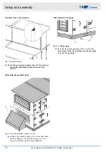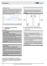
Fig. 36: Hydraulic system connection (example)
①
Supply air unit
②
Extract air unit
③
hydraulic unit
IN
Flow
OUT Return
3.
Connect the heat exchanger with the hydraulic
If there are several heat exchangers in airflow
direction, connect the pipes in series.
The position of the connection points is given in
the order-specific approval drawing.
If you are in doubt about the position of any pipes
to be connected, please get in touch with our
Technical Service.
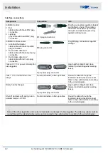
Heat exchanger connection
Connection on
hydraulic unit
Heat
exchanger
Air handling
unit
Description
IN-ETA
IN
Flow – extract
air
OUT-ETA
OUT
Return –
extract air
IN-SUP
IN
Flow – supply
air
Connection on
hydraulic unit
Heat
exchanger
Air handling
unit
Description
OUT-SUP
OUT
Return –
supply air
4.
Run-around coil systems with external feeding:
Make the required connections ( Fig. 36 ).
Connections for external feeding
Connection on
hydraulic unit
External feeding
IN-CO
Water flow – cooling
OUT-CO
Return – cooling
IN-HE
Water flow – heating
OUT-HE
Return – heating
Ventilation device
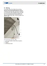
For optimum ventilation of the heat exchanger, we rec-
ommend that you install suitable air separators at the
highest points of the system (e.g., above the air han-
dling unit), which reduce the airflow velocity by
increasing the cross section and can thus be ideally
used for deaerating glycol systems.
Fig. 37: Air separator with cross section enlargement
Installation
Connecting the run around coil system
Air handling unit X-CUBE X2 / X-CUBE X2 compact
40
Содержание X-CUBE X2
Страница 69: ...Appendix Appendix Air handling unit X CUBE X2 X CUBE X2 compact 69...
Страница 71: ...A Adjusting the storage mass Adjusting the storage mass Air handling unit X CUBE X2 X CUBE X2 compact 71...
Страница 72: ...Montageanleitung Mounting Instructions KLINGENBURG Ausrichtung der Speichermasse Adjustment of storage mass...


