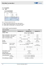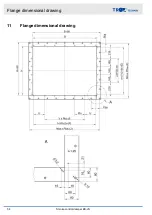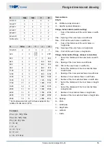
7.4.4 B24D and B230D
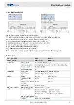
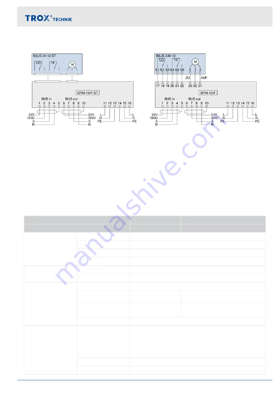
Fig. 29: Wiring example for attachments B24D and B230D
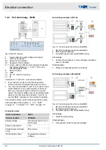
Check whether the damper blades move correctly from OPEN to CLOSED during commissioning.
The mode switch allows you to choose one of the following operating modes:
Automatic (damper is controlled via the bus; status LEDs are not active)
Maintenance (damper is controlled via the bus; status LEDs are not active)
NC contact, manual (bus commands are overridden)
NO contact, manual (bus commands are overridden)
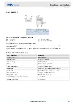
The actuator and the control module are factory wired.
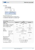
Technical data for the actuator,
Chapter 7.3.1 ‘B24 ’ on page 40
.
Technical data
Order code detail
B24D
B230D
Control module
BRM-10-F-ST
BRM-10-F
Electrical data
Supply voltage
18 – 32 V DC (typically 24 V)
Current consumption
5 mA (typically), 26 mA max. (for 100 ms when relays close)
Protection level
IP 20 (EN 60529)
IEC protection class
II
Construction
Digital inputs
2 for feedback from limit switches (volt-free)
Digital outputs
1 for signalling to the fire damper
Outputs
Actuator
24 V DC
24 / 230 V AC
Permanent current,
max.
AC 5 A
DC 5 A
Switch-on current, max.
(< 15 ms)
AC 8 A
DC 8 A
Switch rating
1250 VA / 150 W
Terminals for damper
input
Max. cross-sectional
area of conductors
Solid core: 0.08 – 2.5 mm²
Multi-strand (without ferrule): 0.08 – 2.5 mm²
Multi-strand (insulated ferrule): 0.25 – 1.5 mm²
Multi-strand (non-insulated ferrule): 0.25 – 2.5 mm²
Max. current, terminals
10A
Pre fuse
MCB, 10 A, characteristic B
Electrical connection
Actuator with control module > B24D and B230D
Smoke control damper EK-JS
47
Содержание EK-JS
Страница 53: ...Decommissioning removal and disposal Smoke control damper EK JS 53...
Страница 54: ...11 Flange dimensional drawing Flange dimensional drawing Smoke control damper EK JS 54...
Страница 57: ...Smoke control damper EK JS 57...
Страница 58: ...Smoke control damper EK JS 58...
Страница 59: ...Smoke control damper EK JS 59...

