background image


© Copyright 2018 TRIUMPH BOARD

       This document contains confidential information which can be used by the recipient only for servicing the above product.                                        

                                                                       Reproduction or distribution of any content of this document without permission is strictly forbidden. 


30


 5.2 Upgrade via side buttons 

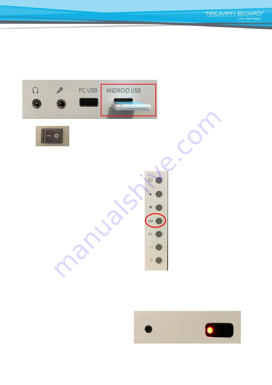
Step 1: Copy the upgrade file “MstarUpgrade.bin” to the root directory in the Udisk; 

Step 2: Insert the Udisk into the “ANDROID-USB” port on the front frame; 


Step 3: After normal shutdown, turn the power switch from “-” to “o” to power off the product; 


Step 4

: Long press the “VOL+” button in the middle of the 7 buttons on the button board at the lower right corner of 

the front fram

e, and also turn the hard switch on the back of the product from “o” to “-” to power on the product; 


Step 5: At this moment, the product will start up, detect the upgrade file and perform upgrade automatically. The 

power indicator light at the lower right corner will start blinking in red; after three times of blinking indicating the 

system has recognized the upgrade file in the Udisk, you can release the “VOL+” button (for some Udisk, their 

indicator light will also blink to indicate the upgrade file is being written); 


Содержание 8592580112638

Страница 1: ...Service Manual Interactive Flat Panel Series 75 EAN 8592580112638 8592580114052 ...

Страница 2: ...ication 6 17 3 1 Machine Specification 6 3 2 Block Diagram of IFP 8 3 3 IFP internal wiring Diagram 10 3 4 MP600S K Power Board 75 10 3 5 Mainboard Parameters 110 3 6 OPS Adapter Board 17 4 Disassembly Steps 18 29 4 1 Tool Preparation 18 4 2 Disassembly Procedure 18 5 Software Debugging Instructions 30 34 5 1 Upgrade via Factory Menu 30 5 2 Upgrade Using side buttons 33 6 Troubleshooting for IFP U...

Страница 3: ...recommended When using the plug be careful not to force the plug into the port When connecting the machine ensure that the port is free from chips that the plug matches the port and that the direction of the plug corresponds to that of the port During use heat generated inside the machine is dissipated via the air inlets outlets on the back of the machine DO NOT use any other object to cover the m...

Страница 4: ...s 7SW button board assembly Version A1 KJ_75 OC_7SW keyboard assembly Version A1 1 Keyboard 5 9032 11JE90 U0001011 KJ_E90 series USB U adapter assembly Version A1 1 Rear adapter board 6 EAN 8592580114601 9046 14JE91 00001011 KJ_E91 light sensor board Version A1 special for technology 1 Light sensor board 7 EAN 8592580114618 9018 11JE93 00001011 KJ_E93 AV board Version A1 1 Front adapter board 8 90...

Страница 5: ... 71Y1 75E89K A3110001 75E89K C2 White aluminum face frame assembly TRIUMPH BOARD logo 1 Metal face frame assembly 2 71Y2 75E89K A6140001 75E89K C2 rear shell of gray sheet metal TRIUMPH BOARD 1 Metal rear shell Screen assembly 1 EAN 8592580114540 7422 750LGK 3I5A9071 75 TFT K750WD90 LA450A1 LED backlight screen RGB 12V 51pin UHD 10bit 60Hz structure 9 18 electrical 6 27 500mA aluminum face frame o...

Страница 6: ...Sub HDMI Max resolution 4K 2K 60Hz HDMI 19 pin SMT horizontal socket USB Support USB flash drive USB mobile hard drive if the load exceeds 500mA a power supply should be additionally equipped by user USB mouse and keyboard etc USB2 0 4 pin USB horizontal socket USB3 0 9 pin USB RJ45 10M 100Mbps SPDIF Max transmission speed 16Mbps Optical fiber terminal Power supply Input power SB5V normal power su...

Страница 7: ...icture Touch frame Enables touch function Front adapter board Front extended OPS PC USB port front extended HDMI port front extended Touch USB port front extended MEDIA USB port extended MIC port extended headset port Rear adapter board Extended OPS PC USB port rear extended Touch USB port RS232 adapter board uses the standard DB9 RS232 port allowing RS232 remote control PC module Built in PC modu...

Страница 8: ...ght sensor board Acquires the value of ambient light and sends it to the mainboard Touch frame adapter board Converts serial port signals to USB signals to provide touch signals for Android mainboard IR board Receives remote control signals from the remote control and sends them to the mainboard Keyboard Acquires button signals and sends them to the mainboard OPS adapter board OPS port to HDMI por...

Страница 9: ...of MP600S K Power Board MP600S K is a multi output power board with the total output power of 502 5W it outputs voltages of 5VSB 5V 12V and 24V also it is equipped with a short circuit over current over voltage protection circuit 3 4 2 Definition of Power Board Socket Pins Socket Pin Definition Function CON4 1 2 AC L AC INPUT LINE 3 NC NC 4 5 AC N AC INPUT NEUTRAL CN201 1 2 7 8 11 GND GROUND 3 4 5...

Страница 10: ...bution of any content of this document without permission is strictly forbidden 10 12 24V GROUND 13 BK ON Backlight ON OFF 14 ADJ Backlight Adjust PWM CN202 1 2 3 24V 24V DC OUTPUT 4 5 6 GND GROUND CN203 1 2 3 12V 12V DC OUTPUT 4 5 6 GND GROUND CN206 1 2 3 4 5 6 LED LED RETURN 7 8 NC NC 9 10 11 12 LED LED OUTPUT 3 5 Mainboard Parameters 3 5 1 Picture of MSD6A828 Mainboard ...

Страница 11: ... the HDMI4 port can achieve the resolution of 3840x2160 60Hz other HDMI ports can only achieve up to 1920x1080 60Hz Formats supported by USB mobile storage device picture movie music File Type Supported File Formats File Name Suffixes Image JPEG BMP PNG jpg bmp png Video MPEG1 MPEG2 MPEG4 H264 RM RMVB MOV MJPEG VC1 DivXFLV avi mpg dat vob div mov mkv rm rmvb m p4 mjpeg ts trp wmv asf flv Audio MP3...

Страница 12: ...IR 9 NC No Connection 4 IR_R Red LED indicator 10 KEY1 Menu Vol Vol 5 IR_G Green LED indicator 11 KEY0 Source CH CH Power 6 GND Ground 12 GND Ground J452 40pin 2 0mm LVDS interface 60HZ Pin No SYMBOL DESCRIPTION Pin No SYMBOL DESCRIPTION 1 GND Ground 21 E2 RXE2 2 VCC Power supply for panel 22 E2 RXE2 3 GND Ground 23 E1 RXE1 4 VCC Power supply for panel 24 E1 RXE1 5 NC No Connection 25 E0 RXE0 6 VC...

Страница 13: ...product Reproduction or distribution of any content of this document without permission is strictly forbidden 13 17 E3 RXE3 37 O0 RXO0 18 E3 RXE3 38 O0 RXO0 19 EC RXEC 39 GND GROUND 20 EC RXEC 40 GND GROUND J455 51pin 2 0mm 60HZ V by One connector J8 2pin 2 0mm OPS CTRL interface Pin No Name Description Pin No Name Description 1 2 GND Ground ...

Страница 14: ... 5V power Supply 4 DP USB_D 2 WIFI EN NO Connection 5 GND GND 3 DM USB_D J104 5pin 2 0mm I2C interface Pin No Name Description Pin No Name Description 1 VCC 3 3V 4 SDA I2C_SDA 2 GND GND 5 NC NO Connection 3 SCL I2C_SCL J9 2pin 2 0mm FAN interface Pin No Name Description Pin No Name Description 1 VCC 12V 2 GND Ground CON11 CON12 CON13 CON15 5pin 2 0mm USB interface Pin No Name Description Pin No Na...

Страница 15: ... 15 3 6 OPS Adapter Board 3 6 1 Picture of OPS Adapter Board Definition of Ports Pin Definition 1 OPS control 2 HEADSET OUT 3 USB3 0 4 HDMI OUT 5 USB2 0 6 USB2 0 7 DC 12V 4 Disassembly Steps 4 1Tool Preparation You will need screwdriver needle nose pliers slotted screwdriver needle nose pliers and slotted screwdriver are used in case of any stripped screw or breaking off hexagonal copper pillar 4 ...

Страница 16: ...bution of any content of this document without permission is strictly forbidden 16 1 Remove speaker Remove Φ3 6mm Plated black zinc mechanical screw with meson head Φ7mm 8PCS release the speaker bracket and rear shell and then pull out the cable of speaker 2 Remove Φ3 6mm Plated black zinc mechanical screw with meson head Φ7mm 7PCS release the rear shell and the IO baffle ...

Страница 17: ...roduction or distribution of any content of this document without permission is strictly forbidden 17 3 Remove Φ3 6mm Plated black zinc mechanical screw with meson head Φ7mm 4PCS release the rear shell and the power strip shield 4 Remove M4 6 black zinc plated cross recessed small button head product screw 14PCS release the rear shell and the face frame ...

Страница 18: ...ent only for servicing the above product Reproduction or distribution of any content of this document without permission is strictly forbidden 18 5 Remove M4 6 black zinc plated cross recessed small button head product screw 11PCS release the rear shell and the panel 6 Remove 6pcs of M3 11mm cross head screws ...

Страница 19: ...oduction or distribution of any content of this document without permission is strictly forbidden 19 7 Remove M6 18 B headband cushion the thickness of the cushion 1 4 plated black zinc mechanical screw 4 PCS release the handle and the face frame 8 Manually remove the M4 25mm cross head screws 4 Pcs release the rear shell and the Corner decorative cover ...

Страница 20: ...s document without permission is strictly forbidden 20 Step 2 Remove boards The rear cover of this product consists of 12 components including Mainboard Power board OPS adapter board Touch frame adapter board RS232 adapter board T CON board rear adapter board front adapter board IR board Keyboard light sensor board speaker Tidy up the cable before removing the boards See the figure below 1 Mainboa...

Страница 21: ...nt contains confidential information which can be used by the recipient only for servicing the above product Reproduction or distribution of any content of this document without permission is strictly forbidden 21 Mainboard cable 2 Power board ...

Страница 22: ...idential information which can be used by the recipient only for servicing the above product Reproduction or distribution of any content of this document without permission is strictly forbidden 22 Power board cable 3 OPS adapter board OPS adapter board cable ...

Страница 23: ...ins confidential information which can be used by the recipient only for servicing the above product Reproduction or distribution of any content of this document without permission is strictly forbidden 23 4 Rear adapter board Rear adapter board cable ...

Страница 24: ...on which can be used by the recipient only for servicing the above product Reproduction or distribution of any content of this document without permission is strictly forbidden 24 5 RS232 port adapter board 6 IR board 7 Keyboard 8 Touch frame adapter board 9 Light Sensor board ...

Страница 25: ...onfidential information which can be used by the recipient only for servicing the above product Reproduction or distribution of any content of this document without permission is strictly forbidden 25 10 Front adapter board 11 T CON board 12 Touch frame 75 ...

Страница 26: ...ntent of this document without permission is strictly forbidden 26 Steps for replacing the touch frame Step 1 Remove the M3 11mm recessed cross head screw black plated zinc alloy tooth machine 6PCS release the rear cover and the front frame Step 2 Manually remove the M4 25mm cross head screws 4 Pcs release the rear shell and the Corner decoration cover Step 2 Remove the Touch frame cable ...

Страница 27: ...he touch end to withdraw the touch frame PCBA at the nonconforming position then install a conforming board into the touch frame in the same way as before 5 Software Debugging Instructions There are two common modes of system software upgrade Upgrade via Factory Menu and Upgrade Using side buttons 5 1 Upgrade via Factory Menu Step 1 Copy the upgrade file MstarUpgrade bin to the root directory in t...

Страница 28: ... distribution of any content of this document without permission is strictly forbidden 28 Step 3 Press the Source key on the remote control when Source options appear on the screen press the numerical keys 2 5 8 0 to enter the Factory Menu _ Step 4 In the Factory Menu select Other Options Upgrade Main click OK and select Confirm then click OK again to start upgrade ...

Страница 29: ...l successful upgrade is achieved and the normal boot screen appears If you did your upgrade correctly swipe up function should be replaced by 2 fingers touch gesture menu and new application OfficeSuite should be visible in the app section OPS use If you are using OPS it is necessary to install driver for 2 fingers touch gesture menu working under OPS Please insert the USB flash disk to the PC USB...

Страница 30: ...er switch from to o to power off the product Step 4 Long press the VOL button in the middle of the 7 buttons on the button board at the lower right corner of the front frame and also turn the hard switch on the back of the product from o to to power on the product Step 5 At this moment the product will start up detect the upgrade file and perform upgrade automatically The power indicator light at ...

Страница 31: ... and new application OfficeSuite should be visible in the app section OPS use If you are using OPS it is necessary to install driver for 2 fingers touch gesture menu working under OPS Please insert the USB flash disk to the PC USB when installing the 2 touch android driver for OPS Notes Do not power off during upgrade Do not un plug USB disk during upgrade Applicable only for EAN 8592580112638 5 3...

Страница 32: ...ervicing the above product Reproduction or distribution of any content of this document without permission is strictly forbidden 32 1 Open Apps menu 2 Click on System Upgrade 3 Press Checking to see if there is any upgrade Notes Do not power off during upgrade Do not un plug Wi Fi Dongle or LAN cable from IFP during upgrade ...

Страница 33: ...by inside and outside temperature difference of glass Under normal conditions the phenomenon will disappear after being used for 3 5 days Replace TV main board Replace OPS adapter board NO NO Upgrade Firmware NO Power indicator can t be turned on Ensure the power cable is connected and plugged into a good known wall outlet YES Check that whether there is 5VSB voltage in certain pin of TV power boa...

Страница 34: ...rd Replace the OPS adapter board NO Dark Replace OPS adapter board NO Replace TV main board NO Replace the Relay board NO Replace TV main board NO No touch Only no touch on Internal and External PC Replace TV main board YES Re plug the touch cable or replace it NO Only no touch on the Internal PC Replace TV main board No touch on Android channel Whether the touch cable connected well with touch fr...

Страница 35: ...ther the mode of internet and wires connection are correct YES YES NO Use a notebook substitute the IFP to check that whether network is ok Re upgrade Android system Replace TV main board YES YES NO Restore router s factory settings Replace router module NO NO Only no sound on pc source Check that the sound setting and sound drive is normal or not Re install the windows system YES No sound on all ...

Страница 36: ...lic EU Phone 420 224 910 221 Fax 420 224 910 218 E mail info triumphboard com www triumphboard com Notices Every effort has been made to ensure all information contained in this user guide is correct but the accuracy or completeness is not guaranteed Before using this product you must evaluate it and determine if it is suitable for your intended application You assume all risks and liability assoc...

Отзывы: