background image

6

GB

Step 1:

Fit the Outer Bearings (H) to the Sliding Insert (A) 

using the M6 x 20 Screws (I) and M6 Hex Nuts 

(J) as shown. Ensure they are fitted on the same 

side of the slider as the three small holes. Fit the 

Inner Bearings (K) to the Sliding Insert using the 

M6 x 45 Screws (L) and M6 Flange Nuts (M). Do 

not yet tighten. All bearings should be parallel to 

the sides of the sliding insert.
Fit the Bosses (O) from underneath the two 

central holes in the sliding insert and attach the 

Main Body (B) to the sliding insert by tightening 

the M6 x 30 Hex Bolts (P) and Washers (Q) 

through the captive nuts in the main body.
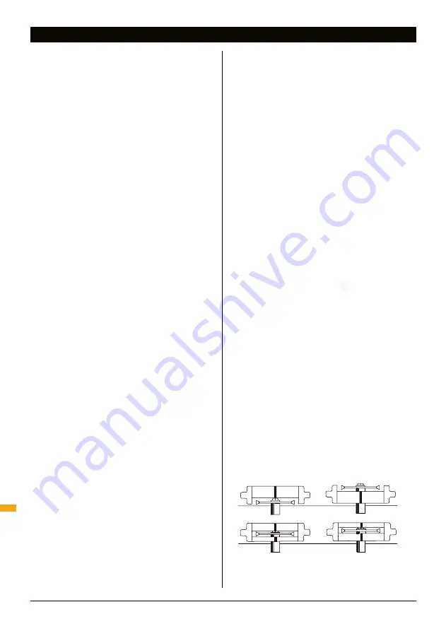
Loosen off the depth stop screws on the 

underneath of the sliding insert to allow 

approximately 29mm movement of the spring-

loaded plunger. (Fig.4)

Step 2:

Slide the zinc locking pin on the underside of the 

main body to the central 'lock' position.
Fit the sliding insert into the router table tracks 

by locating the slots on the inner bearings onto 

the flange on the aluminium inner track. Now 

firmly tighten the inner bearing screws and 

check that the sliding insert slides smoothly. If 

there is any float between the aluminium inner 

track and the inner bearings, loosen the screws, 

twist the bearing slightly and re-tighten.
The lock pin on the main body should locate 

in the slot on the router plate. 

In use: 

When 

a safety guard is depressed the lock pin is 

released, allowing the fence to slide in the 

direction the guard is depressed. The fence will 

automatically spring back to its central position.

Note: 

If the fence does not freely spring back, 

loosen the fit of the inner bearings against the 

aluminium track, or spray the track with spray 

lubricant.
Screw the Inner Clamp Knobs (N) onto the inner 

bearing screws, they cut their own thread.  

In use: 

When fitting or removing the sliding 

insert the cut-away edges of the clamps must 

face toward the inner track. During operation 

turn the cut-away edges away from the inner 

track. Do not over-tighten, the sliding insert 

should be held down yet free to slide.
Check that the biscuit joiner is level with or 

slightly above the table surface and if necessary 

to remove it and adjust the height of the 

aluminum inner track on the router table 

Step 3:

Remove the Biscuit Joiner Cutter (C) from its 

storage position in the end of the main body.
If you have a 

1

4

" router, remove the 

1

4

" Shank 

(D) from its storage position in the end of the 

main body. If tight, gently prise it out using a 

screwdriver. Unbolt the cutting disc from the 

1

2

shank and refit it to the 

1

4

" shank. Do not over-

tighten. Store the unused 

1

2

" shank in place of 

the 

1

4

" shank in the end of the main body. 

Remove the biscuit joiner from the table. Fit the 

large insert ring, supplied with the router table, 

to the router plate. Tighten the cutter firmly into 

the router collet.
Adjust the cutter height so that there is 5-7mm 

clearance between the underside of the cutter 

and the router plate. Make sure the router's 

height adjustment is securely locked before use.

Step 4:

Familiarise yourself with the Notched and Slotted 

Windows (E & F). They reduce the risk of finger 

entry into the cutter zone and improve saw dust 

extraction. The windows are reversible so that 

the two sets cover the full range of cutter height 

adjustment from 5-25mm above the table. 

The cutter should never be set any higher than 

25mm above the router plate. (Fig.1)
To remove the windows push outwards, from the 

inside, near each side of the window.

When re-fitting, use the safety guards to push 

them fully home. Store the unused pair of 

windows in the holes provided on the sliding 

guide.

Assembly

ASSEMBLY

5 - 10

10 - 15

15 - 20

10 - 15

15 - 20

20 - 25

20 - 25

5 - 10

Fig.1

Содержание BJA 300

Страница 1: ...s com Operating and Safety Instructions Bedienings en veiligheidsvoorschriften Instructions d utilisation et consignes de sécurité Gebrauchs und Sicherheitsanweisung Istruzioni Per L uso E La Sicurezza Instrucciones de uso y de seguridad ...

Страница 2: ... its unique design Keep this manual close to hand and ensure all users of this tool have read and fully understand the instructions Contents Symbols Symbols 2 Parts list 3 Safety 4 Assembly 6 Operating 8 Warranty 9 SYMBOLS Always wear ear eye and respiratory protection Conforms to relevant legislation and safety standards Instruction warning Do not use before viewing and fully understanding the op...

Страница 3: ... E Notched Windows 2 F Slotted Windows 2 G Sliding Guide 1 H Outer Bearing 2 I M6 x 20 Screw 2 J M6 Hex Nut 2 K Inner Bearing 2 L M6 x 45 Screw 2 M M6 Flange Nut 2 N Inner Clamp Knob 2 O Boss 2 P M6 x 30 Hex Bolt 2 Q Washer 2 R Sliding Guide Clamp 1 S Coach Bolt 1 T Round Knob with M6 Nut 1 Fastener bag contents ...

Страница 4: ... wearing eye protection dust mask non slip safety shoes hard hat and hearing protection used in appropriate conditions will reduce personal injuries c Avoid accidental starting Ensure the switch is in the Off position before plugging in Carrying power tools with your finger on the switch or connecting to power with the switch on the On position invites accidents d Remove any adjusting key or wrenc...

Страница 5: ...ccordance with these instructions and in the manner intended for the particular type of power tool taking into account the working conditions and the work to be performed Failure to use the tool for its intended purposes could result in a hazardous situation and may invalidate the warranty 5 SERVICE a Have your power tool serviced by a qualified repair technician using only identical replacement p...

Страница 6: ...s they cut their own thread In use When fitting or removing the sliding insert the cut away edges of the clamps must face toward the inner track During operation turn the cut away edges away from the inner track Do not over tighten the sliding insert should be held down yet free to slide Check that the biscuit joiner is level with or slightly above the table surface and if necessary to remove it a...

Страница 7: ...cleaner for sawdust extraction It can be used without dust extraction but you will need to lift the main body after every 20 30 cuts to clean out accumulated shavings While any vacuum cleaner can be used domestic bag type units can fill up very quickly For a much larger capacity we recommend fitting a Triton Dust Collector DCA300 to your vacuum cleaner Screw the vacuum hose left hand thread suppli...

Страница 8: ...the height of the cutter above the router plate by using the height adjustment mechanism of your router It is not normally necessary to exactly centre the cuts on the edge or end of the wood but make sure you have at least 3mm of material on either side of the biscuit Fig 7 As long as you always lay your wood with the good or seen face down on the table the slots in matching pieces will always lin...

Страница 9: ...pt as proof of purchase Hand Held Operation Triton Precision Power Tools guarantees to the purchaser of this product that if any part proves to be defective due to faulty materials or workmanship within 12 MONTHS from the date of original purchase Triton will repair or at its discretion replace the faulty part free of charge This guarantee does not apply to commercial use nor does it extend to nor...

Отзывы:

Похожие инструкции для BJA 300