background image

47

FLUID MANIFOLD SERVICE AND REPAIR

REPACKING FLUID MANIFOLD (CON'T)

21. Insert a pair of needle nose pliers into the slots on the top of the piston rod. Pry up on the Piston Rod and turn it to

align the slots front to back.

22. Use a 1" open end or an adjustable wrench to tighten the upper retainer (#6) in Diagram A firmly.

23. Slide the slots of the piston rod onto the connecting rod.

24. Gently turn the fan in either direction and it will draw the pump assembly up to the crank housing. Be careful to

make sure the alignment pins line up while seating the pump housing.

25. Attach the transducer to the back of the pump housing. Make sure the o-ring (#18) in Diagram C, is in place

before threading it in. Tighten it firmly with a 3/4" open end wrench, while holding the steel tubing with a pair of
pliers.

26. Use a 5/16" Socket Wrench to insert the two hex bolts into the bottom of the pump housing and tighten firmly.

27. Replace the Front Cover (#11) in Diagram B.

28. Replace the Motor Cover and tighten the three screws (#1) snug.

29. Re-attach the suction assembly. Make sure to apply some packing grease to the two o-rings (#4) in Diagram E

before inserting the elbow into the intake valve assembly. Push the elbow straight in until it stops. Thread the nut
(#1) in Diagram E back onto the intake valve assembly snugly, but hand-tight.

REPLACING THE PRIME / SPRAY VALVE

1.

Using a 3/32" punch, knock out the pin (#29) from the black handle (#28) in Diagram A.

2.

Remove the black handle and cam exposing the prime/spray valve (#27) in Diagram A.

3.

Using a 3/4" open end or adjustable wrench, remove the prime/spray valve and inspect. Replace if worn or

leaking.

REPLACING THE MANIFOLD FILTER

1.

Remove the filter housing (#1) in Diagram A from the pump housing. New pumps from the factory will be tight and

you will need to use an adjustable wrench to loosen.

2.

Remove the filter (#3) and the filter core (#4) in Diagram A. Clean both components and if the filter is damaged or

worn, replace.

3.

When screwing the filter housing back in, make sure it is snug but hand-tight.

Содержание 600-830

Страница 1: ...h Industries Inc 610 Rahway Avenue Union NJ 07083 PH 908 378 1080 FAX 908 378 1659 www tritechindustries com PROFESSIONAL AIRLESS SPRAYER MAXIMUM WORKING PRESSURE 3300PSI 227BAR 22 7MPa VOLTS FOR THE APPLICATION OF ARCHITECTURAL PAINTS AND COATINGS VOLTS CYCLES AMPS PHASE 110V 50 60 13 SINGLE 220V 50 60 7 SINGLE REV 8 2022 T7 Owners Manual 302 116 ...

Страница 2: ... 220V AUS 600 836 T7 LO CART COMPLETE 110V 600 846 T7 LO CART COMPLETE 220V 600 858 T7 LO CART COMPLETE 110V UK 600 871 T7 LO CART COMPLETE 220V AUS 501 150 T380 AIRLESS SPRAY GUN 200 517 T93R CONTRACTOR TIP 200 999 CONTRACTOR GUARD 400 114 50 X AIRLESS HOSE 120 625 5000 PSI GAUGE KIT 600 834 T7 HI CART COMPLETE 110V 600 844 T7 HI CART COMPLETE 220V 600 853 T7 HI CART COMPLETE 110V UK 600 870 T7 H...

Страница 3: ... ensure extensions cord ground prong is intact WARNING Improper installa on of the grounding plug may result in a risk of electric shock When repair or replacement of the cord or plug is required do not connect the grounding wire to either flat blade mains terminal The wire with the green or green yellow insula on is the grounding wire Check with a qualified electrician or serviceman when the grou...

Страница 4: ...s specified by TriTech Industries Inc Verify that all containers and collec ve systems are grounded to prevent sta c discharge Connect to a grounded outlet and use grounded extension cords Do not use a 2 to 3 adapter Do not use a paint or a solvent containing halogenated hydrocarbons Keep spray area well ven lated Keep a good supply of fresh air moving through the area Keep pump assembly in a well...

Страница 5: ... producing 3300 psi Only use replacement parts or accessories that are specified by TriTech Industries Inc and that are rated at a minimum of 3300 psi Always engage the gun trigger lock when not spraying Verify the gun trigger lock is func oning properly Verify that all connec ons are secure before opera ng the unit Know how to stop the unit and bleed pressure quickly Be thoroughly familiar with t...

Страница 6: ...unded type only o Use only extension cord with plug and receptacle that matches plug supplied on equipment o Inspect the extension cord for damage before use replaced if necessary o Acceptable extension cord lengths 16 AWG 25 feet maximum 12 AWG 50 feet maximum 10 AWG 100 feet maximum Pails Solvent and oil based fluids follow local codes o Use only conduc ve metal pails placed on a grounded surfac...

Страница 7: ...f way Flush 1 minute Inspect for leaks If a leak occurs follow the pressure relief procedure then ghten fi ng were leak occurred Do not a empt to stop leaks with hand or rag Repeat Start up 1 5 again If no leaks proceed 14 Place siphon tube in paint pail 15 Trigger gun again into metal container un l paint appears Move gun to paint pail and trigger for 20 seconds Set the safety to ON posi on Assem...

Страница 8: ...pray valve Trigger gun into flushing pail to purge fluid from hose 12 Open prime spray valve Then close Do not store with prime spray valve open 13 Remove filter from gun and sprayer if installed Clean and inspect Reinstall filters 14 If flushing with water flush again with mineral spirits or TriTech Pump Cleaner to leave a protective coa ng to prevent freezing or corrosion 15 Unplug power cord fr...

Страница 9: ...aser end of a pencil 4 Remove the suction hose and the inlet valve Move the outlet ball with the eraser end of a pencil PUMP BUILDS PRESSURE BUT WILL NOT SHUT OFF 1 The inlet ball or seat are obstructed or chipped 2 Outlet ball or seat are obstructed or chipped 3 Prime valve is leaking 1 Clean or replace if needed 2 Clean or replace if needed 3 Replace the prime valve if coating leaks while under ...

Страница 10: ...längerungskabels intakt ist WARNUNG Unsachgemäße Installa on des Erdungssteckers kann zu Stromschlaggefahr führen Wenn eine Reparatur oder ein Austausch des Kabels oder Steckers erforderlich ist schließen Sie das Erdungskabel nicht an einen der Flachstecker Netzanschlüsse an Der Draht mit der grünen oder grün gelben Isolierung ist der Erdungsdraht Wenden Sie sich an einen qualifizierten Elektriker...

Страница 11: ...systeme geerdet sind um sta sche Entladungen zu vermeiden An eine geerdete Steckdose anschließen und geerdete Verlängerungskabel verwenden Verwenden Sie keinen 2 auf 3 Adapter Verwenden Sie keine Farbe oder Lösungsmi el die halogenierte Kohlenwasserstoffe enthalten Sprühbereich gut belü et halten Sorgen Sie für ausreichend frische Lu die durch den Bereich strömt Bewahren Sie die Pumpenbaugruppe in...

Страница 12: ...hläuche und Teile auf Anzeichen von Beschädigung prüfen Beschädigte Schläuche oder Teile ersetzen Dieses System kann 3300 psi erzeugen Verwenden Sie nur Ersatz oder Zubehörteile die von TriTech Industries Inc angegeben und für mindestens 3300 psi ausgelegt sind Ak vieren Sie immer die Abzugssperre der Pistole wenn Sie nicht spritzen Stellen Sie sicher dass die Abzugssperre der Pistole ordnungsgemä...

Страница 13: ...en Wenn der Sprühschlauch ersetzt werden muss ersetzen Sie ihn nur durch den iden schen Schlauch der mit dem Sprühgerät geliefert wurde Verlängerungskabel nur dreiadriger geerdeter Typ o Verwenden Sie nur Verlängerungskabel mit Stecker und Steckdose die zum mitgelieferten Stecker passen o Untersuchen Sie das Verlängerungskabel vor dem Gebrauch auf Beschädigungen und ersetzen Sie es gegebenenfalls ...

Страница 14: ...t met uw handen of een poetslap Herhaal stap 1 5 voor het opstarten Ga door als er geen lekken zijn 15 Leg de hevelslang in de emmer met verf 16 Druk de trekker van het in het blik gerichte spuitpistool opnieuw in totdat u verf ziet Breng het spuitpistool naar de verfemmer en druk de trekker 20 seconden in Zet de vergrendeling op AAN Breng de p en de bescherming aan Zie volgende onderdeel TIP EN B...

Страница 15: ...istool naar de emmer met spoelvloeistof en houd het tegen de emmer aan gedrukt Vuur het spuitpistool af om het systeem grondig te spoelen Laat de trekker los en zet de trekkervergrendeling op AAN 9 Draai de drukafvoerklep omlaag en laat de spoelvloeistof 1 2 minuten doorspoelen om de afvoerslang schoon te maken 10 Breng de hevelslang omhoog tot boven de spoelvloeistof en laat de verfspuit 15 30 se...

Страница 16: ...ren 5 Zet de vergrendeling van het spuitpistool vast 6 Open de drukafvoerklep Houd de drukafvoerklep open totdat u weer met spuiten begint NBBewaar het apparaat niet langdurig met de drukafvoerklep open Bewaar het apparaat in de spuitstand NBAls u vermoedt dat de spui p of de slang helemaal is verstopt of dat de druk na het volgen van de bovenstaande stappen niet is verwijderd draait u de tipbesch...

Страница 17: ...der abgebrochen 2 Auslasskugel oder Sitz sind verstopft oder abgebrochen 3 Entlüftungsventil ist undicht 1 Reinigen oder bei Bedarf ersetzen 2 Bei Bedarf reinigen oder ersetzen 3 Ersetzen Sie das Entlüftungsventil wenn die Beschichtung unter Druck austritt FARBE AUS NASSEM BECHER AUSLAUFEN 1 Überprüfen Sie die obere Verpackung 1 Ersetzen Sie bei Bedarf die obere Packung PUMPENLEISTUNG IST NIEDRIG ...

Страница 18: ...t et le cas échéant assurez vous que la broche de terre de la rallonge est intacte AVERTISSEMENT Une mauvaise installa on de la fiche de mise à la terre peut entraîner un risque d électrocu on Lorsque la répara on ou le remplacement du cordon ou de la prise est nécessaire ne connectez pas le fil de mise à la terre à l une ou l autre des bornes secteur à lame plate Le fil avec l isola on verte ou v...

Страница 19: ...s et autour de la zone de pulvérisa on doivent être correctement mises à la terre pour les protéger contre les décharges sta ques et les é ncelles U lisez uniquement des tuyaux de pulvérisa on de peinture sans air haute pression conducteurs ou mis à la terre spécifiés par TriTech Industries Inc Vérifiez que tous les conteneurs et systèmes collec fs sont mis à la terre pour éviter les décharges d é...

Страница 20: ...s d injec on consultez immédiatement un médecin Vérifiez les tuyaux et les pièces pour des signes de dommages Remplacez tous les tuyaux ou pièces endommagés Ce système est capable de produire 3300 psi U lisez uniquement des pièces de rechange ou des accessoires spécifiés par TriTech Industries Inc et évalués à un minimum de 3300 psi Verrouillez toujours la gâche e du pistolet lorsque vous ne pulvé...

Страница 21: ...les et des surfaces chaudes Si le tuyau de pulvérisa on doit être remplacé remplacez le uniquement par un tuyau iden que fourni avec le pulvérisateur Cordon prolongateur type à trois fils avec mise à la terre uniquement o U lisez uniquement une rallonge avec une fiche et une prise correspondant à la fiche fournie sur l équipement o Inspectez la rallonge avant u lisa on remplacez la si nécessaire o...

Страница 22: ...ite se produit suivez la procédure de décompression puis serrez le raccord en cas de fuite eu lieu N essayez pas d arrêter les fuites avec la main ou un chiffon Répétez le démarrage 1 5 à nouveau S il n y a pas de fuite con nuez 15 Placez le tube du siphon dans le seau de peinture 16 Ac onnez à nouveau le pistolet dans le récipient métallique jusqu à ce que la peinture apparaisse Déplacez le pisto...

Страница 23: ...endant 15 à 30 secondes pour vidanger le liquide Coupez l alimenta on 11 Fermez la vanne d amorçage de pulvérisa on Déclenchez le pistolet dans le seau de rinçage pour purger le liquide du tuyau 12 Ouvrez la vanne d amorçage de pulvérisa on Puis fermez Ne pas entreposer avec la vanne d amorçage de pulvérisa on ouverte 13 Re rez le filtre du pistolet et du pulvérisateur s il est installé Ne oyer et...

Страница 24: ... HUMIDE 1 Inspecter la garniture supérieure 1 Remplacer la garniture supérieure si nécessaire LE DÉBIT DE LA POMPE EST FAIBLE 1 La buse de pulvérisation pourrait être usée 2 Les billes d entrée ou de sortie sont usées 3 La soupape d amorçage est usée 1 Inspectez la pointe en vérifiant la largeur du motif en éventail S il est usé remplacez le 2 Vérifiez que les billes d entrée et de sortie ne sont ...

Страница 25: ...ón esté intacta ADVERTENCIA La instalación incorrecta del enchufe de conexión a erra puede resultar en un riesgo de descarga eléctrica Cuando sea necesario reparar o reemplazar el cable o el enchufe no conecte el cable de conexión a erra a ninguno de los terminales de alimentación de clavija plana El cable con aislamiento verde o verde amarillo es el cable de conexión a erra Consulte con un electr...

Страница 26: ... la clavija de conexión a erra del cable de extensión esté intacta ADVERTENCIA La instalación incorrecta del enchufe de conexión a erra puede resultar en un riesgo de descarga eléctrica Cuando sea necesario reparar o reemplazar el cable o el enchufe no conecte el cable de conexión a erra a ninguno de los terminales de alimentación de clavija plana El cable con aislamiento verde o verde amarillo es...

Страница 27: ...es Inc Verificar que todos los contenedores y sistemas colec vos estén conectados a erra para evitar descargas está cas Conéctelo a un tomacorriente con conexión a erra y use cables de extensión con conexión a erra No u lice un adaptador de 2 a 3 No u lice pinturas o disolventes que contengan hidrocarburos halogenados Mantenga el área de aplicación bien ven lada Mantenga un buen suministro de aire...

Страница 28: ...exión a erra o U lice únicamente un cable de extensión con enchufe y receptáculo que coincida con el enchufe suministrado en el equipo o Inspeccione el cable de extensión en busca de daños antes de usarlo reemplácelo si es necesario o Longitudes de cable de extensión aceptables 16 AWG 25 pies máximo 12 AWG 50 pies máximo 10 AWG 100 pies máximo Baldes Fluidos a base de aceite y solventes siga los c...

Страница 29: ...o 11 Encienda la alimentación 12 Aumente la presión para arrancar el motor y permita que el fluido circule a través del tubo de alivio de presión durante 15 segundos luego baje la presión 13 Coloque la válvula de alivio de presión en posición horizontal Quite el seguro del ga llo de la pistola rociadora 14 Sostenga la pistola contra el contenedor de metal conectado a erra Dispare la pistola y aume...

Страница 30: ...tar el ga llo con núe mueve el arma LIMPIEZA DE LA PUNTA OBSTRUIDA a Suelte el ga llo ponga el seguro en ON b Gire la punta T93R para que la flecha apunte hacia atrás c Quite la seguridad d Dispare la pistola para despejar la obstrucción Nunca apunte el arma a su mano o a un trapo VOLVER A ROCIAR a Ac ve la seguridad b Regrese la boquilla a la posición de rociado c Quite el seguro y con núe rocian...

Страница 31: ... la manguera y la pistola con un trapo empapado en agua o alcohol mineral PROCEDIMIENTO DE ALIVIO DE PRESIÓN La presión del rociador debe aliviarse manualmente para evitar que el rociador arranque o rocíe accidentalmente El fluido a alta presión puede inyectarse a través de la piel y causar lesiones graves Para reducir el riesgo de lesiones por inyección salpicaduras de líquido o piezas móviles Si...

Страница 32: ...s 2 La bola de salida o el asiento son obstruido o astillado 3 La válvula de cebado tiene fugas 1 Limpie o reemplace si es necesario 2 Limpie o reemplace si es necesario 3 Reemplace la válvula de cebado si el recubrimiento se filtra mientras está bajo presión PINTURA FUGA DE COPA HÚMEDA 1 Inspeccione el empaque superior 1 Reemplace el empaque superior si es necesario LA SALIDA DE LA BOMBA ES BAJA ...

Страница 33: ...bruikt zorg ervoor dat de aardingspin van het verlengsnoer intact is WAARSCHUWING Onjuiste installa e van de aardingsstekker kan leiden tot een risico op elektrische schokken Wanneer repara e of vervanging van het snoer of de stekker nodig is mag de aardingsdraad niet worden aangesloten op een van de pla e netvoedingsklemmen De draad met de groene of groen gele isola e is de aarddraad Neem contact...

Страница 34: ...ceerd door TriTech Industries Inc Controleer of alle containers en collec eve systemen geaard zijn om sta sche ontlading te voorkomen Sluit aan op een geaard stopcontact en gebruik geaarde verlengsnoeren Gebruik geen 2 naar 3 adapter Gebruik geen verf of oplosmiddel dat gehalogeneerde koolwaterstoffen bevat Spuitruimte goed geven leerd houden Zorg voor een goede toevoer van frisse lucht door het g...

Страница 35: ...t lichaam injecteren en erns g lichamelijk letsel veroorzaken Zoek onmiddellijk medische hulp in het geval dat er een injec e plaatsvindt Slangen en onderdelen op beschadigingen controleren Vervang beschadigde slangen of onderdelen Dit systeem kan 3300 psi produceren Gebruik alleen vervangende onderdelen of accessoires die zijn gespecificeerd door TriTech Industries Inc en die een nominale waarde ...

Страница 36: ...k alleen een verlengsnoer met een stekker en een stopcontact dat overeenkomt met de stekker die op de apparatuur is geleverd o Controleer het verlengsnoer voor gebruik op beschadigingen vervang het indien nodig o Aanvaardbare verlengsnoerlengtes 16 AWG maximaal 25 voet 12 AWG maximaal 50 voet 10 AWG 100 voet maximaal Emmers Vloeistoffen op basis van oplosmiddelen en olie volg de plaatselijke voors...

Страница 37: ... volg dan de drukontlas ngsprocedure en draai de fi ng vast als er lekkage is opgetreden Probeer lekken niet met de hand of een doek te dichten Herhaal Opstarten 1 5 opnieuw Ga verder als er geen lekken zijn 15 Plaats de sifonbuis in de verfemmer 16 Spuit het pistool opnieuw in de metalen container totdat er verf verschijnt Verplaats het pistool naar de verfemmer en druk de trekker gedurende 20 se...

Страница 38: ...en verplaats de inlaatkogel met het gumuiteinde van een potlood 4 Verwijder de zuigslang en de inlaatklep Verplaats de uitlaatbal met het gumuiteinde van een potlood POMP BOUWT DRUK OP MAAR SLUIT NIET UIT 1 De inlaatkogel of zitting is verstopt of gechipt 2 Uitlaatkogel of zitting zijn belemmerd of afgebroken 3 Vulklep lekt 1 Reinig of vervang indien nodig 2 Reinig of vervang indien nodig 3 Vervang ...

Страница 39: ...es Inc 610 Rahway Avenue Union NJ 07083 U S A 302 119B Models T4 T5 T7 T8 T9 T11 Part Number 599 800 599 802 599 804 599 806 599 810 599 812 599 814 599 816 599 818 599 827 599 829 600 800 600 802 600 804 600 806 600 810 600 812 600 814 600 816 600 818 600 827 600 829 600 830 600 832 600 834 600 836 600 840 600 842 600 844 600 846 601 834 601 836 601 844 601 846 602 804 602 806 602 814 602 816 602...

Страница 40: ...anufactured by August 27 2021 TriTech Industries Inc 610 Rahway Avenue Union NJ 07083 U S A 302 119B Models T360 T380 T420 T720 T750 T370IL Part Number 500 150 500 151 500 152 500 153 500 150 GTH 500 152 GTH 501 150 501 155 501 251 501 255 501 150 GTH 501 155 GTH 503 150 503 151 503 152 503 153 503 150 GTH 503 152 GTH 506 150 506 151 506 152 506 153 507 150 507 151 507 152 507 153 ...

Страница 41: ...ve 2011 65 EU 8June2011 the product manufactured by TriTech Industries do not contain materials that exceed thresholds for cadmium mercury hexavalent chromium Polybrominated diphenyl ethers PBDEs or other regulated substances Safety Compliance Statement Tritech Industries product are cer fied mee ng UL 1450 Issued 2010 05 05 Ed 4 Rev 2013 11 01 Motor Operated Air Compressors Vacuum Pumps Pain ng E...

Страница 42: ...PSI 227BAR 3050 210 BAR 200 3300PSI 227BAR 3000 207 BAR 250 3300PSI 227BAR 2950 203 BAR 300 3300PSI 227BAR 2900 199 BAR VERTICAL 50 3200 220BAR 3135 216 BAR 100 3200 220BAR 3070 211 BAR 150 3200 220BAR 3005 209 BAR 200 3200 220BAR 2940 202 BAR 250 3200 220BAR 2875 198 BAR 300 3200 220BAR 2810 193 BAR EXTENSION CORD VOLTAGE DROP LINE LOSS 1 4 HOSE STANDARD LATEX PAINT AT PUMP AT TIP ...

Страница 43: ...eve pressure Stop spraying Have to check or service your equipment Are installing or cleaning the spray tip PRESSURE RELIEF PROCEDURE 1 Turn the pressure control knob all the way to the left to stop the unit from pumping 2 Turn the On Off switch to the OFF position 3 Unplug the power cord from the wall 4 Hold the metal part of the gun firmly to a grounded metal container and trigger the gun to rel...

Страница 44: ... 5 7 8 28 27 29 10 25 12 24 21 17 23 22 20 19 9 11 6 26 35 13 14 15 16 18 32 33 31 30 PLEASE REMOVE THE BLACK PACKING HOLDER PRIOR TO PACKING INSTALLATION PLEASE REMOVE THE BLACK PACKING HOLDER PRIOR TO PACKING INSTALLATION 34 36 REV 8 2022 ...

Страница 45: ...24 LOWER PACKING 1 12 600 099 75 PISTON ROD 1 13 600 047 UPPER BALL 1 14 101 001 O RING 1 15 600 142 75 PISTON VALVE 1 16 600 090 75 PISTON ROD COMPLETE Includes 12 15 1 17 600 022 LOWER BALL 1 18 600 021 INTAKE VALVE SEAT 1 19 600 234 GASKET 1 20 600 013 INTAKE VALVE HOUSING 1 21 600 279 O RING 1 22 600 353 O RING 1 23 600 367 O RING 1 24 600 087 GUIDE BALL PISTON 1 25 599 199 HEX BOLT 2 26 600 1...

Страница 46: ...vise and use a 1 open end or adjustable wrench to remove the upper retainer 6 in Diagram A 12 Remove the piston rod 12 in Diagram A by tapping the top of the piston rod with a rubber mallet 13 Remove the upper packing 8 and lower packing 11 in Diagram A Inspect both the upper and lower backings for wear If you do not intend to replace the packings do not remove them 14 When replacing the packings ...

Страница 47: ... 27 Replace the Front Cover 11 in Diagram B 28 Replace the Motor Cover and tighten the three screws 1 snug 29 Re attach the suction assembly Make sure to apply some packing grease to the two o rings 4 in Diagram E before inserting the elbow into the intake valve assembly Push the elbow straight in until it stops Thread the nut 1 in Diagram E back onto the intake valve assembly snugly but hand tigh...

Страница 48: ...ludes 5 14 15 16 18 1 6 600 546 MOTOR 220V Includes 5 14 15 16 18 1 7 600 178 REDUCER GEAR 1 8 600 185 75 CRANKSHAFT 1 9 600 307 THRUST WASHER 1 10 600 317 CRANK HOUSING 1 11 600 316 SCREW 4 12 600 113 FRONT COVER 1 13 600 0108 CONNECTING ROD 1 14 600 581 BRUSHES 110V SET OF 2 1 14 600 582 BRUSHES 220V SET OF 2 1 15 600 356 FAN 1 16 600 494 SNAP RING 1 17 302 059 LABEL FIRE EXPLOSION 1 18 600 438 ...

Страница 49: ...600 366 SWITCH TO BOARD WIRE 110V 1 10 600 366 SWITCH TO BOARD WIRE 220V 2 11 600 364 POTENTIOMETER 1 ITEM PART DESCRIPTION QTY 12 600 592 LOCK WASHER 2 13 600 419 O RING 2 14 600 264 1 EDGE LINER 6 75 Long 1 15 600 123 KNOB 1 16 600 271 GROMMET 1 17 600 401 SCREW 3 18 600 418 O RING 1 19 600 036 TRANSDUCER 1 20 600 337 GROMMET 1 21 600 288 CONTROL BOARD BOX 110V 1 21 600 289 CONTROL BOARD BOX 220...

Страница 50: ...tor BLACK Motor BLACK Motor RED Motor 600 121 Switch Circuit Breaker 120V DIAGRAM D DIAGRAM D 600 151 Power Cord Ground Wire 600 366 Red 600 364 Potentiometer 600 036 Transducer RED Motor MOTOR 600 124 Switch Circuit Breaker 220V T7 220V WIRING DIAGRAM T7 110V WIRING DIAGRAM A C INPUT A C INPUT NEG POS MOTOR NEG POS ...

Страница 51: ...screws 1 and remove control box cover 2 in Diagram C 2 Unplug the transducer wire gray and posi ve and nega ve motor leads red black from the circuit board on Diagram D E 3 Loosen transducer nut with a open end wrench and slide transducer out of the back of the pump housing Use a pair of needle nose pliers to hold the transducer while loosening the nut 4 Remove 3 screws 17 Diagram C Make sure to f...

Страница 52: ...order When reinstalling motor brushes make sure to have red and black wire leads to the back of the motor housing REPLACE MOTOR Follow pressure relief procedure before attempting to serviceor repair unit If trouble shoo ng guide suggests replacing the motor follow the directions below REMOVE MOTOR 1 Remove 3 screws 1 Diagram B and remove motor cover 3 Diagram B 2 Remove 6 screws 1 Diagram C and re...

Страница 53: ...re to the circuit board Diagram D E 10 Rea ach the BLACK and RED motor leads to the circuit board Diagram D E 11 Insert 6 screws 1 to rea ach the control box cover 2 both in Diagram C 12 Slide the motor cover 3 Diagram B back onto the motor and insert 3 screws 1 to a ach 13 Insert 4 screws 1 to a ached the front cover 11 all in Diagram B REPLACE GEARS CONNECTING ROD Follow pressure relief procedur...

Страница 54: ... FILTER 600 066 30 SUCTION FILTER 30 MESH REV 11 2021 DIAGRAM F ITEM PART NUMBER DESCRIPTION QTY 1 600 233 NUT 1 2 600 168 WASHER 1 3 600 236 SNAP RING 1 4 600 164 O RING 2 5 600 066 15 SUCTION FILTER 15 MESH 1 6 600 542 HOSE CLAMP 1 7 600 442 HOSE CLIP 1 8 600 213 SUCTION HOSE ASSEMBLY 1 10 600 212 PRIME HOSE 1 ...

Страница 55: ...PTION QTY 1 600 542 HOSE CLAMP 1 2 600 406 O RING 1 3 600 396 SUCTION TUBE D I 1 4 600 471 HOSE CLIP 1 5 600 512 PRIME HOSE 1 6 600 085 10 SUCTION FILTER 10 MESH 1 OPTIONAL SUCTION FILTER 600 085 15 SUCTION FILTER 15 MESH 600 085 30 SUCTION FILTER 30 MESH REV 11 2021 1 2 3 6 4 5 DIAGRAM G ...

Страница 56: ...00 381 PIN 2 15 600 379 WASHER 2 16 600 378 HANDLE GUIDE 2 17 600 391 BUTTON SNAP 2 18 600 375 HI CART COMPLETE Excludes 1 2 5 1 19 600 429 LO CART BASE FRAME 1 20 600 430 LO CART COMPLETE Excludes 5 1 1 1 2 2 6 5 3 4 LO CART HI CART STAND FRAMES STAND NOTE All of the parts needed to complete the lo cart frame are listed above with the hi cart frame HI CART LO CART 7 8 9 5 10 19 20 11 12 13 14 15 ...

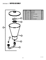
Страница 57: ...TY 1 600 570 CLIP SPRING 1 2 600 569 FILTER DISC 1 3 600 531 HOPPER Lid Included 1 4 600 562 GASKET 1 5 600 539 HOPPER TUBE Includes 6 1 6 600 164 O RING 2 7 600 556 HOPPER ASSEMBLY 1 HOPPER ASSEMBLY REV 2 2022 5 4 3 2 1 6 7 DIAGRAM J ...

Страница 58: ...58 NOTES ...

Страница 59: ...59 NOTES ...

Страница 60: ...e equipment does not disclose any defect in material or workmanship repairs will be made at a reasonable charge which charges may include the cost of parts labor and transporta on THIS WARRANTY IS EXCLUSIVE AND IS IN LIEU OF ANY OTHER WARRANTIES EXPRESS OR IMPLIED INCLUDING BUT NOT LIMITED TO WARRANTY OF MERCHANT ABILITY OR WARRANTY OF FITNESS OR A PARTICULAR PURPOSE TriTech s sole obliga on and b...

Отзывы: