
17
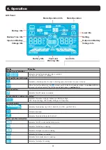
4. Operation
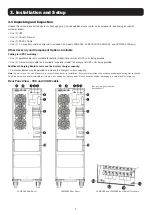
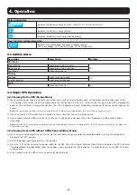
4.4.3 Connecting Devices to UPS
1) After the UPS has been turned on, devices may be connected and powered on one at a time. The UPS system’s LCD panel will display
the total load level.
2) When connecting devices with inductive loads (such as a printer), the in-rush current should be calculated carefully to confirm it meets
the capacity of the UPS. Power consumption of such loads may cause an overload.
3) If the UPS is overloaded, the alarm will beep twice every second.
4) In case of overload, remove non-essential devices immediately. To prevent overload and ensure system safety, it is recommended to
have the total load connected to the UPS at no more than 80% of its nominal power capacity.
5) If the overload time is higher than the acceptable time listed in On-line Mode, the UPS will automatically transfer to Bypass Mode. After
the overload is removed, the UPS will return to On-line Mode. If the overload time is higher than the acceptable time listed in Battery
Mode, the UPS will go to fault status. At this time, if the bypass is enabled, the UPS will supply power to the load via bypass. If the
bypass function is disabled or the input power is not within acceptable bypass range, it will directly cut off output.
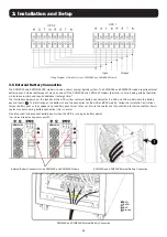
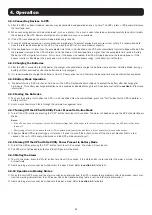
4.4.4 Charging the Batteries
1) After the UPS is connected to utility power, the charger will automatically charge the batteries (except when in Battery Mode, during a
battery self-test, overload or when the batteries are fully charged).
2) It is recommended to charge the batteries at least 10 hours prior to use. Otherwise, the backup time may be shorter than expected.
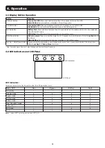
4.4.5 Battery Mode Operation
1) The default value is 990 minutes, or 16.5 hours. The UPS will automatically shut down to protect the battery after discharging for
16.5 hours. This battery discharge protection can be enabled or disabled through the LCD control panel (refer to
section 4.7
for more
information).
4.4.6 Testing the Batteries
1) To check the battery status when the UPS is in On-line Mode/Freq. Converter Mode, press the “Test” button for the UPS to perform a
battery self-test.
2) Users may set battery self-tests through the network management card.
4.4.7 Turning Off the UPS with Utility Power Present in On-line Mode
1) Turn off the UPS inverter by pressing the “OFF” button for at least 0.5 seconds. The alarm will beep once and the UPS will enter Bypass
Mode.
Notes:
• If the UPS has been set to bypass output, it will bypass voltage from utility power to the output terminal, even though the UPS inverter has been
turned off.
• After turning off the UPS, be aware that the UPS is operating in Bypass Mode and there is risk of power loss for connected devices.
2) In Bypass Mode, UPS output voltage is still present. In order to cut off the output, switch off the line input breaker. Within a few
seconds, the unit’s LCD panel will be blank and the UPS will be completely off.
4.4.8 Turning Off the UPS with No Utility Power Present in Battery Mode
1) Turn off the UPS by pressing the “OFF” button for at least 0.5 seconds. The alarm will sound once.
2) The UPS will cut off power to output and the LCD panel will be blank.
4.4.9 Muting the Alarm
1) To mute the alarm, press the “Mute” button for at least 0.5 seconds. If the Mute button is pressed after the alarm is muted, the alarm
will reactivate.
2) Some warning alarms cannot be muted unless the error is fixed. Refer to
section 4.3
for details.
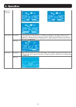
4.4.10 Operation in Warning Status
1) When the Fault LED flashes and the alarm sounds once every second, the UPS is encountering problems with its operation. Users may
view the warning indicator from the LCD panel. Check the troubleshooting table in section 6 for more information.
2) Some warning alarms cannot be muted until the error is fixed. Refer to
section 4.3
for details.
Содержание S3M30KX
Страница 125: ...125 2 4 2 5 2 6 2 7 TN 4 2 EN IEC 62040 1...
Страница 127: ...127 3 3 1 1 1 1 RS 232 1 1 5 S3M30KX S3M30KX NIB S3M40KX S3M40KX NIB 1 1 4 30K 40K S3M30KX S3M40KX S3M30KX S3M40KX...
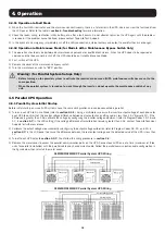
Страница 128: ...128 3 60K 80K S3M60KX S3M80KX S3M60KX S3M80KX 1 RS 232 2 USB 3 EPO 4 5 6 SNMP WEBCARDLX 7 8 9 10 11 12 11 12 13 14...
Страница 129: ...129 3 3 2 1 1 3 1 2 3 2 3 5 3 1 3 2...
Страница 132: ...132 3 OFF R S T N 3 4 3 7 1 2 3 5 3 R S T N R S T N 4 5 6 7 8 S3M30KX S3M40KX 2 1...
Страница 135: ...135 4 H M S Fault Warning 4 9 4 11 VAC VDC Hz 0 25 26 50 51 75 76 100 ECO...
Страница 144: ...144 4 11 2 HS H 3 YES NO 12 2 N L 3 DIS ATO CHE Enter CHE Enter CHE 13 2 Add Sub 3 0 9 9 0 14 2 Add Sub 3 0 9 9 0...
Страница 147: ...147 4 2...
Страница 148: ...148 ECO ECO 4...
Страница 149: ...149 4 CVCF CF 50 60 4...
Страница 150: ...150 2 CVCF Test 0 5 I P 4...
Страница 151: ...151 4 3 4 11 4 9...
Страница 153: ...153 4 4 10 EPO 4 11 4 11 01 21 02 22 04 33 3 30 05 34 07 3A 08 3C 09 3D 0A 3E 0B EPO 3F 0D 40 0E...
Страница 155: ...155 6 EPO EPO OFF EPO 43 14 15 16 17 18 19 7 02 4 7 3 CHE Enter CHE Enter L2 L3 L2 L3...
Страница 156: ...156 7 7 1 40 C 90 6 24 24 3 7 2 BUS 7 3 Tripp Lite S3MX 1 0 40 C 2 25 C 3 24 7 4 Tripp Lite...


