


UP
DOWN
A
E
B
C
D
8
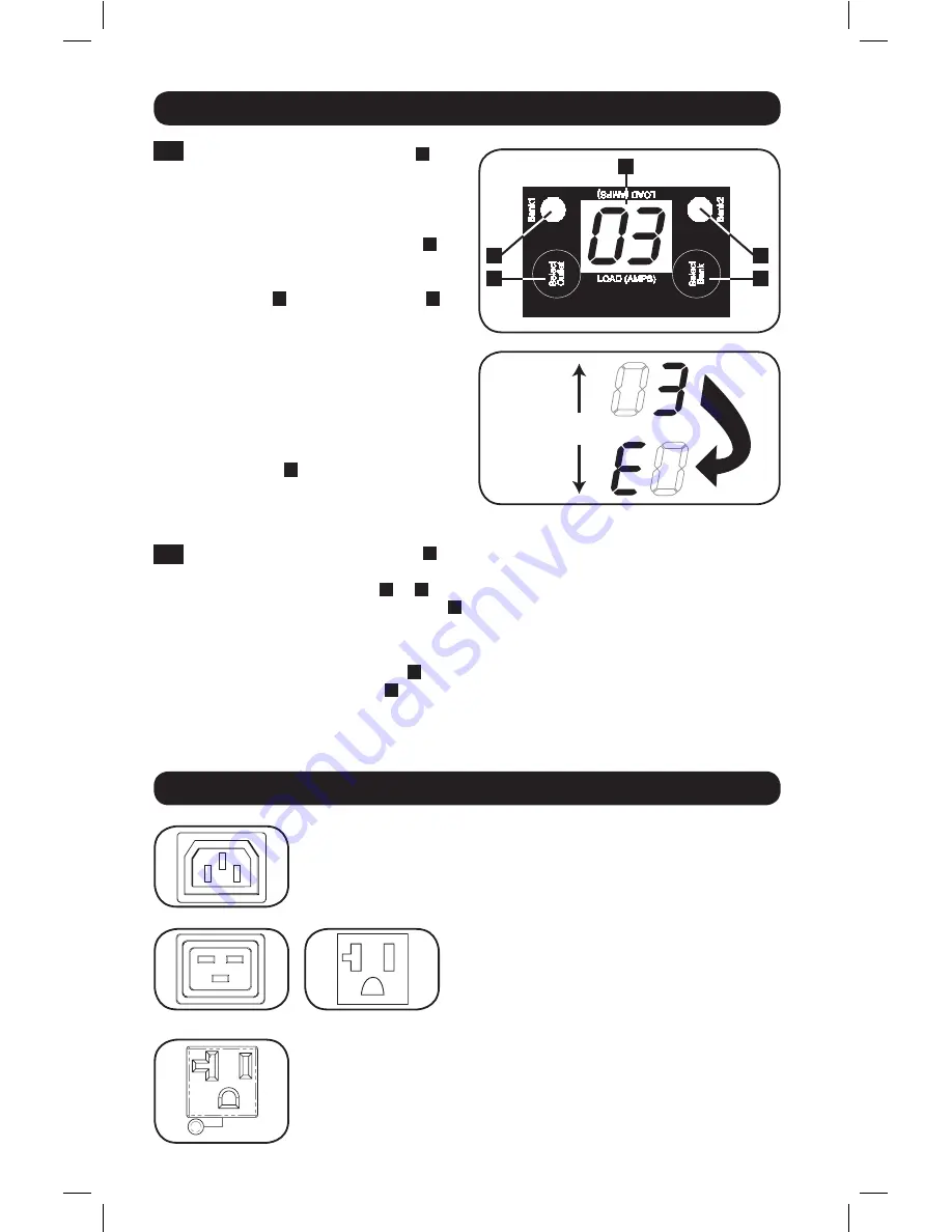
Digital Load Meter
1
Select Bank Button:
This button
A
can be pressed to show total current for
each bank. Pressing this button once
will display the total current for all of
the Bank 1 outlets, located nearest to
the input cord. The LED for Bank 1
D
will illuminate and the total Amp current
for Bank 1 outlets will display on the
LED screen
C
. Pressing this button
A
a second time will produce the same
results for Bank 2. Pressing the button a
third time will display total PDU current
and both Bank 1 and Bank 2 LEDs will
light. Pressing the button additional
times will repeat the cycle.
If you press and hold this button for
four seconds, the numbers in the LED
Amps display
C
will flip for mounting
versatility. The unit can be mounted with
the power cord facing the top or bottom
while still being able to read the display.
2
Select Outlet Button:
This button
B
can be pressed to show the current for each
individual outlet. The LED located next to the selected outlet and the LED for the Bank
to which the outlet belongs (
D
or
E
) will flash when the total current for that outlet is
displayed (in amps) on the LED screen
C
. Pressing this button a second time will produce
the same results for outlet 2, pressing a third time for outlet 3 and so on through all the
outlets.
If you press and hold this button
B
for 4 seconds you can display the IP Address assigned
to the unit in the LED screen
C
. The default is no address assigned. If this is the case,
“
no address
” will display, one letter at a time. If there is an IP Address programmed, the
address will display 1 digit at a time with dashes (-) representing dots or periods (.).
Features
Outlets:
During normal operation, the outlets distribute AC power to
connected equipment.
Outlet LED:
Once the unit is powered-on, each outlet individually ramps
up and each outlet LED will illuminate when the associated outlet is ready
to distribute live AC power.
IEC-60320-C13
IEC-60320-C19
NEMA 5-15/20R
16-10-211-933668.indb 8
12/22/2016 11:36:18 AM