background image

59

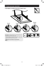
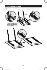
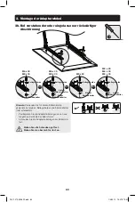
3. Montage der Adapterwinkel

3a. Für flache Hinterfolien

Schutzstreifen

Adapterhalterung

Entfernen Sie alle 
Schrauben von den 
Schutzstreifen. Entfernen 
Sie die Schutzstreifen.

M5 x 14  

M6 x 14 

M8 x 20

Beilagscheibe

Hinweis:

 Verwenden Sie für diesen Bildschirmtyp geeignete 

Schrauben, Beilagscheiben und Abstandhalter (falls erforderlich).
•   Positionieren Sie die Adapterhalterungen so nah wie möglich 

an der Mitte des Bildschirms.

•  Schrauben Sie die Adapterhalterungen am Bildschirm fest.

         Ziehen Sie alle Schrauben gut fest.  

       Ziehen Sie sie aber nicht zu fest an.

18-11-270-9338F2.indb   59

1/4/2019   10:47:36 AM

Содержание DWFPSC4570M

Страница 1: ...SA www tripplite com support Copyright 2019 Tripp Lite All rights reserved 200 x 200 300 x 300 200 x 400 400 x 400 400 x 600 70 MAX 110 lb 50 kg MAX PROTECT YOUR INVESTMENT Register your product for quicker service and ultimate peace of mind You could also win an ISOBAR6ULTRA surge protector a 100 value www tripplite com warranty Español 14 Français 27 Русский 40 Deutsch 53 18 11 270 9338F2 indb 1...

Страница 2: ...e If the product should prove defective in material or workmanship within that period Seller will repair or replace the product in its sole discretion THIS WARRANTY DOES NOT APPLY TO NORMAL WEAR OR TO DAMAGE RESULTING FROM ACCIDENT MISUSE ABUSE OR NEGLECT SELLER MAKES NO EXPRESS WARRANTIES OTHER THAN THE WARRANTY EXPRESSLY SET FORTH HEREIN EXCEPT TO THE EXTENT PROHIBITED BY APPLICABLE LAW ALL IMPL...

Страница 3: ... support for service Vertical Wall Plate x2 M5 x 14 Screw x4 Adapter Bracket x2 M5 x 8 Screw x8 Bubble Level x1 Combo Lock x1 Horizontal Wall Plate x2 M6 x 14 Screw x4 Anchor Bolt x6 Washer x4 M8 x 20 Screw x4 Concrete Anchor x6 Small Spacer x8 M6 x 30 Screw x4 D6 Washer x6 Big Spacer x8 M8 x 30 Screw x4 Security Bar x1 Package M Package W 18 11 270 9338F2 indb 3 1 4 2019 10 47 06 AM ...

Страница 4: ...all Plate Horizontal Wall Plate M5 x 8 M5 x 8 Bubble Level Attach the vertical wall plates to the horizontal wall plates using the appropriate screws Tighten all screws with a proper screwdriver 18 11 270 9338F2 indb 4 1 4 2019 10 47 07 AM ...

Страница 5: ...RNING Make sure that mounting screws are anchored into the center of the studs Use of a stud finder is highly recommended Installers are responsible to provide hardware for other types of mounting situations Installers must verify that the supporting surface will safely support the combined load of the equipment and all attached hardware and components 18 11 270 9338F2 indb 5 1 4 2019 10 47 08 AM ...

Страница 6: ...id sections can generally be found 25 mm 1 toward the middle of the block from either end An electric drill on a slow setting is suggested to drill the hole rather than a hammer drill so as to avoid breaking out the back of the hole when entering a hollow section Installers must verify that the supporting surface will safely support the combined load of the equipment and all attached hardware and ...

Страница 7: ...ve strips M5 x 14 M6 x 14 M8 x 20 Washer Note Choose appropriate screws washers and spacers if necessary according to the type of screen Position the adapter brackets as close as possible to the center of the display Screw the adapter brackets onto the display Firmly secure all screws Do not over tighten 18 11 270 9338F2 indb 7 1 4 2019 10 47 10 AM ...

Страница 8: ...er Big Spacer M6 x 30 M8 x 30 M8 x 20 M6 x 30 M8 x 30 M8 x 20 Note Choose appropriate screws washers and spacers if necessary according to the type of screen Position the adapter brackets as close as possible to the center of the display Screw the adapter brackets onto the display Firmly secure all screws Do not over tighten 18 11 270 9338F2 indb 8 1 4 2019 10 47 11 AM ...

Страница 9: ...ter Brackets 3b For Protruded or Recessed Back Screen continued Protective Strips Reattach the protective strips to the adapter brackets using the previously removed screws 18 11 270 9338F2 indb 9 1 4 2019 10 47 12 AM ...

Страница 10: ... display with attached adapter brackets over the top of the mounted wall plate Make sure the bracket is correctly mounted and the safety straps are locked securely before releasing the display Open the kickstands to hold the display Wall Wall Wall Wall 18 11 270 9338F2 indb 10 1 4 2019 10 47 13 AM ...

Страница 11: ...ide Security Bar through the Mounting Brackets and Attach Combo Lock to Secure Security Bar Combo Lock Security Bar Insert the security bar to the secure the rail 18 11 270 9338F2 indb 11 1 4 2019 10 47 13 AM ...

Страница 12: ...ity Bar through the Mounting Brackets and Attach Combo Lock to Secure Security Bar Security Bar Fold the kickstands after finishing the security bar installation Wall Wall 18 11 270 9338F2 indb 12 1 4 2019 10 47 14 AM ...

Страница 13: ...t or mechanical lifting equipment carefully lift the display and remove the display from the wall plate Maintenance Check that the bracket is secure and safe to use at regular intervals at least every three months For any additional questions visit www tripplite com support 1111 W 35th Street Chicago IL 60609 USA www tripplite com support 18 11 270 9338F2 indb 13 1 4 2019 10 47 15 AM ...

Страница 14: ... INDICADA PUEDEN OCURRIR LESIONES SEVERAS O DAÑOS A LA PROPIEDAD 1111 W 35th Street Chicago IL 60609 EE UU www tripplite com support Copyright 2019 Tripp Lite Todos los derechos reservados 200 x 200 300 x 300 200 x 400 400 x 400 400 x 600 70 MÁXIMO 110 lb 50 kg MÁXIMO English 1 Français 27 Русский 40 Deutsch 53 18 11 270 9338F2 indb 14 1 4 2019 10 47 15 AM ...

Страница 15: ...ducto y lesiones personales Garantía Limitada por 5 Años El vendedor garantiza este producto si se usa de acuerdo con todas las instrucciones aplicables de que está libre de defectos en material y mano de obra por un período de 5 años a partir de la fecha de compra inicial Si el producto resultara defectuoso en material o mano de obra dentro de ese período el vendedor reparará o reemplazará el pro...

Страница 16: ...ara solicitar servicio Placa de Pared Vertical x2 Tornillo M5 x 14 x4 Soporte Adaptador x2 Tornillo M5 x 8 x8 Nivel de Burbuja x1 Candado de Combinación x1 Placa de Pared Horizontal x2 Tornillo M6 x 14 x4 Tornillo de Anclaje x6 Arandela x4 Tornillo M8 x 20 x4 Taquete x6 Espaciador Pequeño x8 Tornillo M6 x 30 x4 Arandela D6 x6 Espaciador Grande x8 Tornillo M8 x 30 x4 Barra de Seguridad x1 Paquete M...

Страница 17: ... de Pared Horizontal M5 x 8 M5 x 8 Nivel de Burbuja Instale las placas verticales de pared a las placas horizontales de pared usando los tornillos adecuados Apriete todos los tornillos con un desatornillador adecuado 18 11 270 9338F2 indb 17 1 4 2019 10 47 16 AM ...

Страница 18: ...laje ADVERTENCIA Cerciórese que los tornillos de instalación estén anclados en el centro de los travesaños Es muy recomendable usar un detector de vigas Los instaladores son responsables de proporcionar los accesorios para otros tipos de soluciones de instalación Los instaladores deben verificar que la superficie de apoyo soporte con seguridad la carga combinada de todo el hardware y componentes i...

Страница 19: ...ques Las secciones sólidas pueden encontrarse generalmente a 254 mm 1 hacia el centro del bloque en cada extremo Se sugiere utilizar un taladro eléctrico a baja velocidad para barrenar el orificio en vez de un rotomartillo para evitar rotura de la parte posterior del orificio al entrar en una sección hueca Los instaladores deben verificar que la superficie de apoyo soporte con seguridad la carga c...

Страница 20: ...rotección M5 x 14 M6 x 14 M8 x 20 Arandela Nota Elija los tornillos arandelas y espaciadores si fueran necesarios apropiados de acuerdo al tipo de pantalla Coloque los soportes adaptadores tan cerca como sea posible al centro de la pantalla Atornille los soportes del adaptador a la pantalla Asegure firmemente todos los tornillos No apriete en exceso 18 11 270 9338F2 indb 20 1 4 2019 10 47 18 AM ...

Страница 21: ...ande Espaciador Grande M6 x 30 M8 x 30 M6 x 30 M8 x 20 M8 x 30 M8 x 20 Nota Elija los tornillos arandelas y espaciadores si fueran necesarios apropiados de acuerdo al tipo de pantalla Coloque los soportes adaptadores tan cerca como sea posible al centro de la pantalla Atornille los soportes del adaptador a la pantalla Asegure firmemente todos los tornillos No apriete en exceso 18 11 270 9338F2 ind...

Страница 22: ...ara Pantalla con Parte Posterior Cóncava o Convexa continuación Barras de Protección Vuelva a colocar las barras de protección a los soportes del adaptador usando los tornillos retirados anteriormente 18 11 270 9338F2 indb 22 1 4 2019 10 47 19 AM ...

Страница 23: ...l adaptador colocados sobre la parte superior de la placa de pared instalada Asegúrese de que el soporte esté instalado correctamente y de las correas de seguridad están firmemente apretados antes de soltar la pantalla Abra las patas de apoyo para sujetar la pantalla Pared Pared Pared Pared 18 11 270 9338F2 indb 23 1 4 2019 10 47 20 AM ...

Страница 24: ...vés de los Soportes de Instalación e Instale el Candado de Combinación para Asegurarla Barra de Seguridad Candado de Combinación Barra de Seguridad Inserte la barra de seguridad para fijar el riel 18 11 270 9338F2 indb 24 1 4 2019 10 47 21 AM ...

Страница 25: ...ortes de Instalación e Instale el Candado de Combinación para Asegurarla Barra de Seguridad Barra de Seguridad Pliegue las patas de apoyo después de terminar la instalación de la barra de seguridad Pared Pared 18 11 270 9338F2 indb 25 1 4 2019 10 47 21 AM ...

Страница 26: ...n ayudante o equipo de elevación mecánico levante la pantalla y retire con cuidado la pantalla de la placa de pared Mantenimiento Compruebe a intervalos regulares al menos trimestralmente que el soporte esté bien instalado y sea seguro para usarse Para cualquier pregunta adicional visite www tripplite com support 1111 W 35th Street Chicago IL 60609 EE UU www tripplite com support 18 11 270 9338F2 ...

Страница 27: ...QUÉE CELA RISQUERAIT DE CAUSER DES BLESSURES GRAVES OU DES DOMMAGES MATÉRIELS 1111 W 35th Street Chicago IL 60609 USA www tripplite com support Droits d auteur 2019 Tripp Lite Tous droits réservés 200 x 200 300 x 300 200 x 400 400 x 400 400 x 600 177 8 cm 70 po MAX 50 kg 110 lb MAX English 1 Español 14 Русский 40 Deutsch 53 18 11 270 9338F2 indb 27 1 4 2019 10 47 22 AM ...

Страница 28: ...antie limitée de 5 ans Le vendeur garantit ce produit s il est utilisé conformément à toutes les instructions applicables est exempt de tous défauts de matériaux et de fabrication pour une période de 5 ans à partir de la date d achat initiale Si le produit s avère défectueux en raison d un vice de matériaux ou de fabrication au cours de cette période le vendeur s engage à réparer ou remplacer le p...

Страница 29: ...pplite com support pour obtenir de l aide Plaque murale verticale x2 Vis M5 x 14 x4 Support d adaptateur x2 Vis M5 x 8 x8 Niveau à bulle x1 Verrou combo x1 Plaque murale horizontale x2 Vis M6 x 14 x4 Boulon d ancrage x6 Rondelle x4 Vis M8 x 20 x4 Ancrage à béton x6 Petite entretoise x8 Vis M6 x 30 x4 Rondelle D6 x6 Grande entretoise x8 Vis M8 x 30 x4 Barre de sécurité x1 Emballage M Emballage W 18...

Страница 30: ...ale Plaque murale horizontale M5 x 8 M5 x 8 Niveau à bulle Fixer les plaques murales verticales aux plaques murales horizontales en utilisant les vis appropriées Serrer toutes les vis avec un tournevis approprié 18 11 270 9338F2 indb 30 1 4 2019 10 47 23 AM ...

Страница 31: ...e les vis de montage sont ancrées au centre des montants Il est fortement recommandé d utiliser un localisateur de montants Les installateurs sont responsables de fournir la quincaillerie pour tout autre type de situations de montage Les installateurs doivent s assurer que la surface d appui va supporter sans risque la charge combinée de l équipement et de tout le matériel et composants attachés 1...

Страница 32: ...ctions solides des blocs Les sections solides se trouvent habituellement à 25 mm 1 po vers le milieu du bloc à partir de chaque extrémité Il est suggéré d utiliser une perceuse électrique pour percer un trou plutôt qu un marteau perforateur afin d éviter d endommager l arrière du trou en présence d un espace vide Les installateurs doivent s assurer que la surface d appui va supporter sans risque l...

Страница 33: ...protection M5 x 14 M6 x 14 M8 x 20 Rondelle Remarque Choisir les vis les rondelles et les en tretoises appropriées le cas échéant en fonction du type d écran Positionner les supports d adaptateur aussi près du centre de l écran que possible Visser les supports d adaptateur sur l écran Serrer fermement toutes les vis Ne pas trop serrer 18 11 270 9338F2 indb 33 1 4 2019 10 47 24 AM ...

Страница 34: ...ntretoise Grande entretoise M6 x 30 M8 x 30 M8 x 20 M6 x 30 M8 x 30 M8 x 20 Remarque Choisir les vis les rondelles et les en tretoises appropriées le cas échéant en fonction du type d écran Positionner les supports d adaptateur aussi près du centre de l écran que possible Visser les supports d adaptateur sur l écran Serrer fermement toutes les vis Ne pas trop serrer 18 11 270 9338F2 indb 34 1 4 20...

Страница 35: ...adaptateur 3b Pour les écrans en saillie ou à dos encastré suite Bandes de protection Rattacher les bandes de protection aux supports d adaptateur en utilisant les vis enlevées plus tôt 18 11 270 9338F2 indb 35 1 4 2019 10 47 26 AM ...

Страница 36: ... supports d adaptateur attachés sur le dessus de la plaque d assemblage du bras de montage mural S assurer que le support est correctement monté et que les courroies de sécurité sont bien verrouillées en place avant de relâcher l écran Ouvrir les béquilles pour tenir l écran Mur Mur Mur Mur 18 11 270 9338F2 indb 36 1 4 2019 10 47 26 AM ...

Страница 37: ...rs les supports de montage puis fixer le verrou combo pour la retenir en place Barre de sécurité Verrou combo Barre de sécurité Insérer la barre de sécurité pour retenir le rail solidement en place 18 11 270 9338F2 indb 37 1 4 2019 10 47 27 AM ...

Страница 38: ...les supports de montage puis fixer le verrou combo pour la retenir en place Barre de sécurité Barre de sécurité Replier les béquilles après avoir terminé l installation de la barre de sécurité Mur Mur 18 11 270 9338F2 indb 38 1 4 2019 10 47 27 AM ...

Страница 39: ... assistant ou en utilisant de l équipement de levage soulever délicatement l écran puis le retirer de la plaque murale Entretien Vérifier à intervalles réguliers que le support peut être utilisé de façon sûre et sécuritaire au moins tous les trois mois Pour toute question supplémentaire visiter www tripplite com support 1111 W 35th Street Chicago IL 60609 USA www tripplite com support 18 11 270 93...

Страница 40: ...ЙТЕ МАКСИМАЛЬНО ДОПУСТИМЫЙ ВЕС ЭТО МОЖЕТ ПРИВЕСТИ К СЕРЬЕЗНЫМ ТРАВМАМ ИЛИ ИМУЩЕСТВЕННОМУ УЩЕРБУ 1111W 35th Street Chicago IL 60609 USA www tripplite com support Охраняется авторским правом 2019Tripp Lite Перепечатка запрещается 200 x 200 300 x 300 200 x 400 400 x 400 400 x 600 ДО 70 ДО 50 кг English 1 Español 14 Français 27 Deutsch 53 18 11 270 9338F2 indb 40 1 4 2019 10 47 28 AM ...

Страница 41: ...арантии Продавец гарантирует отсутствие изначальных дефектов материала или изготовления в течение 5 лет с момента первоначальной покупки данного изделия при условии его использования в соответствии со всеми применимыми к нему указаниями В случае проявления каких либо дефектов материала или изготовления в течение указанного периода Продавец осуществляет ремонт или замену данного изделия исключитель...

Страница 42: ...я крепления к стене 2 шт Винт M5 x 14 4 шт Переходный кронштейн 2 шт Винт M5 x 8 8 шт Пузырьковый уровень 1 шт Кодовый замок 1 шт Горизонтальная пластина для крепления к стене 2 шт Винт M6 x 14 4 шт Анкерный болт 6 шт Шайба 4 шт Винт M8 x 20 4 шт Анкер для бетона 6 шт Малая проставка 8 шт Винт M6 x 30 4 шт Шайба D6 6 шт Большая проставка 8 шт Винт M8 x 30 4 шт Защитная штанга 1 шт Упаковочный комп...

Страница 43: ...ая пластина для крепления к стене Винт M5 x 8 Винт M5 x 8 Пузырьковый уровень Прикрепите вертикальные пластины к горизонтальным пластинам для крепления к стене с помощью соответствующих винтов Затяните все винты с помощью отвертки соответствующего размера 18 11 270 9338F2 indb 43 1 4 2019 10 47 28 AM ...

Страница 44: ...ние крепежных винтов по центру элементов каркаса С этой целью настоятельно рекомендуется использование детектора неоднородностей Ответственность за обеспечение подходящей крепежной оснастки для других способов монтажа возлагается на установщика Установщик обязан убедиться в том что опорная поверхность с запасом выдержит суммарную нагрузку создаваемую оборудованием и всеми входящими в комплект дета...

Страница 45: ...стях блоков Сплошные части обычно находятся на расстоянии 25 мм от любого из краев блока к его центру Во избежание разрушения задней стенки отверстия при попадании сверла в полую часть для высверливания отверстия рекомендуется использовать электрическую дрель на малой скорости вращения вместо перфоратора Установщик обязан убедиться в том что опорная поверхность с запасом выдержит суммарную нагрузк...

Страница 46: ...те защитные рейки M5 x 14 M6 x 14 M8 x 20 Шайба Примечание Выбирайте подходящие винты шайбы и проставки при необходимости в соответствии с типом экрана Разместите переходные кронштейны как можно ближе к центру дисплея Привинтите переходные кронштейны к дисплею Плотно затяните все винты Не перетягивайте 18 11 270 9338F2 indb 46 1 4 2019 10 47 30 AM ...

Страница 47: ...а Большая проставка Большая проставка M6 x 30 M8 x 30 M8 x 20 M6 x 30 M8 x 30 Винт M8 x 20 Примечание Выбирайте подходящие винты шайбы и проставки при необходимости в соответствии с типом экрана Разместите переходные кронштейны как можно ближе к центру дисплея Привинтите переходные кронштейны к дисплею Плотно затяните все винты Не перетягивайте 18 11 270 9338F2 indb 47 1 4 2019 10 47 31 AM ...

Страница 48: ...онштейнов 3б Для экранов с выпуклой или вогнутой задней стенкой продолжение Защитные рейки Прикрепите защитные рейки обратно к переходным кронштейнам с помощью ранее вывернутых винтов 18 11 270 9338F2 indb 48 1 4 2019 10 47 32 AM ...

Страница 49: ...икрепленными к нему переходными кронштейнами за верхний край установленной пластины для крепления к стене Прежде чем отпустить дисплей необходимо убедиться в том что кронштейн прикреплен надлежащим образом а защитные рейки надежно затянуты Раскройте опорные подставки для поддержки дисплея Стена Стена Стена Стена 18 11 270 9338F2 indb 49 1 4 2019 10 47 32 AM ...

Страница 50: ...тную штангу через монтажные кронштейны и установите кодовый замок для защиты Защитная штанга Кодовый замок Защитная штанга Вставьте защитную штангу для фиксации направляющей 18 11 270 9338F2 indb 50 1 4 2019 10 47 33 AM ...

Страница 51: ...нгу через монтажные кронштейны и установите кодовый замок для защиты Защитная штанга Защитная штанга После завершения установки защитной штанги сложите опорные подставки Стена Стена 18 11 270 9338F2 indb 51 1 4 2019 10 47 33 AM ...

Страница 52: ...ливоспользовавшисьмеханическим подъемнымоборудованием осторожноприподнимитедисплейи снимитеегоспластиныдлякреплениякстене Уход за изделием Регулярно не реже чем раз в три месяца проверяйте надежность крепления кронштейна и безопасность его использования При возникновении вопросов посетите страницу www tripplite com support 1111W 35th Street Chicago IL 60609 USA www tripplite com support 18 11 270 ...

Страница 53: ... WERDEN EINE ÜBERSCHREITUNG KANN ZU SCHWEREN VERLETZUNGEN UND ERHEBLICHEN SACHSCHÄDEN FÜHREN 1111 W 35th Street Chicago IL 60609 USA www tripplite com support Copyright 2019 Tripp Lite Alle Rechte vorbehalten 200 x 200 300 x 300 200 x 400 400 x 400 400 x 600 70 Zoll Max 110 lb 50 kg Max English 1 Español 14 Français 27 Русский 40 18 11 270 9338F2 indb 53 1 4 2019 10 47 34 AM ...

Страница 54: ...tie Der Verkäufer garantiert für einen Zeitraum von fünf Jahren ab Kaufdatum dass das Produkt weder Material noch Herstellungsfehler aufweist wenn es gemäß aller zutreffenden Anweisungen verwendet wird Wenn das Produkt in diesem Zeitraum Material oder Herstellungsfehler aufweist kann der Verkäufer diese Fehler nach eigenem Ermessen beheben oder das Produkt ersetzen DIE NORMALE ABNUTZUNG ODER BESCH...

Страница 55: ...upport Vertikale Wandplatte 2 x Schraube M5 x 14 4 x Adapterwinkel x2 Schraube M5 x 8 8 x Libelle 1 x Kombischloss x1 Horizontale Wandplatte 2 x Schraube M6 x 14 4 x Verankerungsbolzen x6 Beilagscheibe 4 x Schraube M8 x 20 4 x Betonbolzen x6 Kleiner Abstandhalter 8 x Schraube M6 x 30 4 x D6 Beilagscheibe x6 Großer Abstandhalter 8 x Schraube M8 x 30 4 x Sicherheitsbalken x1 Paket M Paket W 18 11 27...

Страница 56: ...tale Wandplatte M5 x 8 M5 x 8 Libelle Befestigen Sie die vertikalen Wandplatten mit den entsprechenden Schrauben an den horizontalen Wandplatten Ziehen Sie alle Schrauben mit einem passenden Schraubendreher fest 18 11 270 9338F2 indb 56 1 4 2019 10 47 34 AM ...

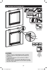
Страница 57: ... Ankerschraube ACHTUNG Stellen Sie sicher dass die Befestigungsschrauben in der Mitte der Balken verankert sind Wir empfehlen die Verwendung eines Balkensuchers Für andere Befestigungsarten muss das Material vom Monteur bereitgestellt werden Stellen Sie sicher dass die verwendete Montagefläche das Gewicht des Geräts sowie das zugehörige Material und sämtliche zugehörigen Komponenten tragen kann 18...

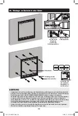
Страница 58: ...egel von jedem Blockende aus 25 mm 1 zur Mitte hin Wir empfehlen beim Bohren des Loches die Verwendung einer elektrischen Bohrmaschine auf geringer Stufe anstatt einer Schlagbohrmaschine um zu vermeiden dass beim Eintritt in einen Hohlraum die Rückseite des Bohrloches einbricht Stellen Sie sicher dass die verwendete Montagefläche das Gewicht des Geräts sowie das zugehörige Material und sämtliche z...

Страница 59: ...20 Beilagscheibe Hinweis Verwenden Sie für diesen Bildschirmtyp geeignete Schrauben Beilagscheiben und Abstandhalter falls erforderlich Positionieren Sie die Adapterhalterungen so nah wie möglich an der Mitte des Bildschirms Schrauben Sie die Adapterhalterungen am Bildschirm fest Ziehen Sie alle Schrauben gut fest Ziehen Sie sie aber nicht zu fest an 18 11 270 9338F2 indb 59 1 4 2019 10 47 36 AM ...

Страница 60: ...andhalter Großer Abstandhalter M6 x 30 M8 x 30 M8 x 20 M6 x 30 M8 x 30 M8 x 20 Hinweis Verwenden Sie für diesen Bildschirmtyp geeignete Schrauben Beilagscheiben und Abstandhalter falls erforderlich Positionieren Sie die Adapterhalterungen so nah wie möglich an der Mitte des Bildschirms Schrauben Sie die Adapterhalterungen am Bildschirm fest Ziehen Sie alle Schrauben gut fest Ziehen Sie sie aber ni...

Страница 61: ...b Bei vorstehender oder eingelassener rückwärtiger Abschirmung Fortsetzung Schutzstreifen Befestigen Sie die Schutzstreifen mit den zuvor entfernten Schrauben erneut an den Adapterklemmen 18 11 270 9338F2 indb 61 1 4 2019 10 47 37 AM ...

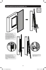
Страница 62: ...n befestigten Adapterwinkeln über die montierte Wandplatte und haken Sie ihn ein Stellen Sie sicher dass die Klemme richtig eingehängt ist und die Sicherungsspangen sicher befestigt sind bevor Sie den Bildschirm loslassen Öffnen Sie die Ständer damit sie den Bildschirm halten Wand Wand Wand Wand 18 11 270 9338F2 indb 62 1 4 2019 10 47 38 AM ...

Страница 63: ...lken durch die Montagewinkel und bringen Sie zur Sicherung das Kombischloss an Sicherheitsbalken Kombischloss Sicherheit sbalken Setzen Sie den Sicherheitsbalken ein um die Schiene zu sichern 18 11 270 9338F2 indb 63 1 4 2019 10 47 38 AM ...

Страница 64: ...h die Montagewinkel und bringen Sie zur Sicherung das Kombischloss an Sicherheitsbalken Sicherheitsbalken Klappen Sie die Ständer nach abgeschlossener Installation des Sicherheitsbalkens ein Wand Wand 18 11 270 9338F2 indb 64 1 4 2019 10 47 39 AM ...

Страница 65: ...eiten Person oder mechanischer Hebevorrichtung vorsichtig an und entfernen Sie den Bildschirm von der Wandplatte Wartung Stellen Sie in regelmäßigen Abständen mindestens alle drei Monate sicher dass die Wandhalterung sicher angebracht ist Weitere Informationen erhalten Sie über www tripplite com support 1111 W 35th Street Chicago IL 60609 USA www tripplite com support 18 11 270 93 38F2_RevA 18 11 ...

Отзывы: